The Challenge
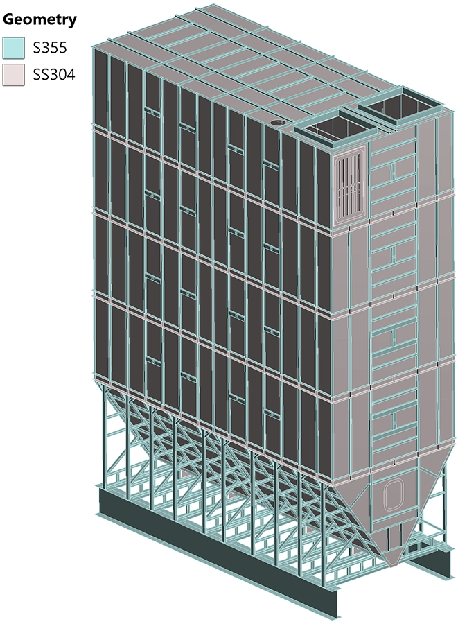
A Belgian manufacturer of industrial storage equipment needed to verify the structural integrity of a rectangular flour silo with a capacity of 40 tonnes. The silo is a welded construction made from SS304 stainless steel plate — in direct contact with the stored flour — reinforced by an external S355 structural steel framework of profiles and tie rods.
Because the silo stores a combustible powder, it must withstand not only the normal operational loads (self-weight and the hydrostatic pressure of 40 tonnes of flour) but also the residual overpressure of a dust explosion after the explosion relief panels have opened. The design had to comply with EN 1990 (Basis of Structural Design), EN 1991-1 (Actions on Structures) and EN 1993-4 (Design of Silos).
Our Approach
We performed a full nonlinear Finite Element Analysis of the complete silo assembly using Ansys Mechanical. The analysis accounted for geometric nonlinearity (large deformations of the thin-walled panels) and nonlinear contact between different structural components.
Geometry preparation and design modifications
The analysis was based on the client-supplied 3D CAD model. During the initial review, several design modifications were recommended and incorporated into the FEA model to improve structural performance: eight profiles were upsized from 40×40×3 mm to 80×40×4 mm, and four additional support consoles (5 mm plate thickness) were added underneath the trough section. Twelve M16 tie rods connect the vertical walls across the silo to resist outward expansion under internal pressure.
Meshing
The entire structure was meshed with 2D HEX shell elements, an approach that captures the bending and membrane behaviour of thin-walled plate structures with high accuracy while keeping the computational cost manageable. Mesh density was set sufficiently fine to resolve stress gradients at geometric transitions and connection points.
Material properties
Two materials were assigned according to Eurocode allowable stress limits. For the SS304 stainless steel panels, the yield strength is 215 MPa, resulting in a maximum allowable stress of 187 MPa (using a partial safety factor γM0 = 1.15). For the S355 structural steel framework, the yield strength of 355 MPa gives an allowable stress of 309 MPa under the same safety factor.
Load cases and combinations
Three individual load cases were defined and then combined into three Ultimate Limit State (ULS) load combinations according to Eurocode:
Load case 1 — Self-weight (QG): gravitational acceleration applied to the entire structure.
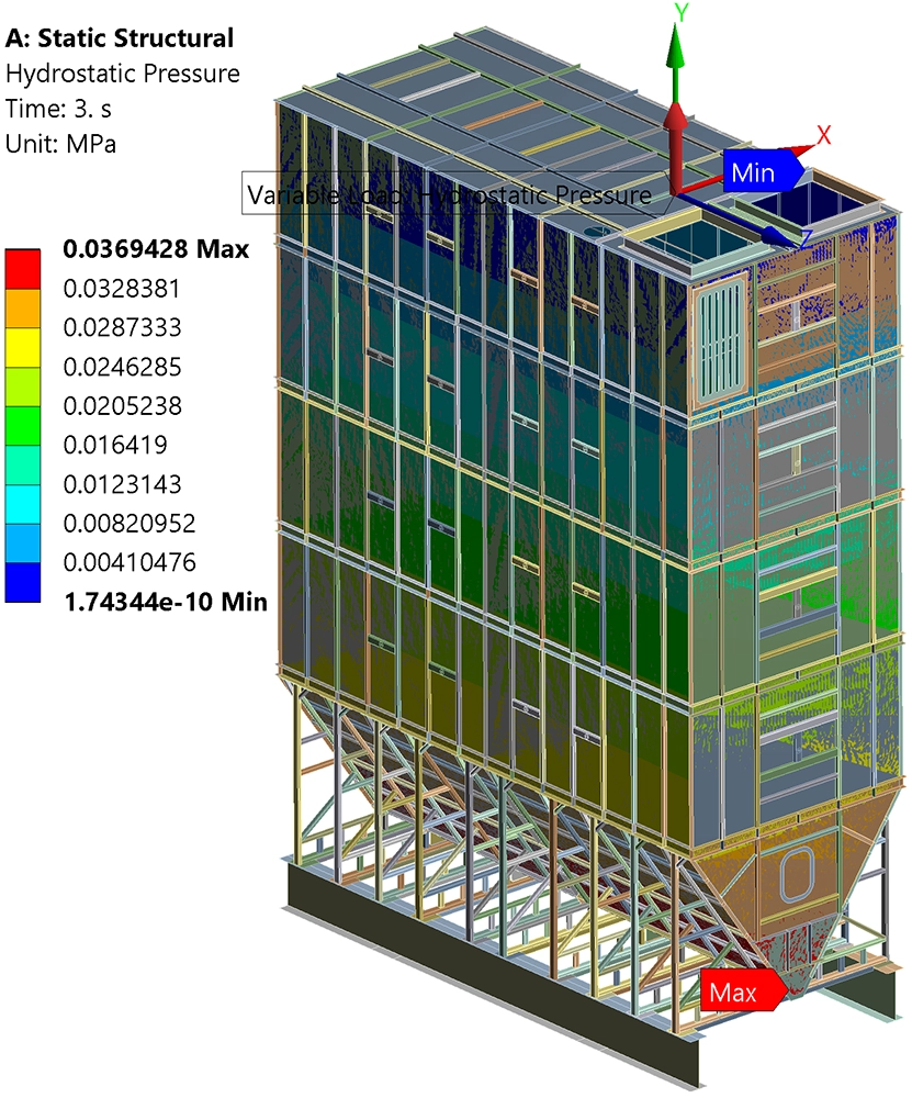
Load case 2 — Hydrostatic pressure (QH): internal pressure from 40 tonnes of flour modelled as a hydrostatic distribution (flour bulk density of 600 kg/m³) on the inner surfaces of the silo.
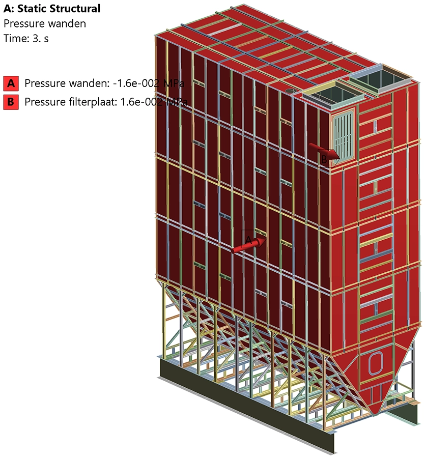
Load case 3 — Dust explosion overpressure (QA): a uniform overpressure of 0.16 bar applied to all internal walls. This represents the reduced explosion pressure (pred) acting on the silo after the two explosion relief panels (total area 1.6 m²) have opened.
The three ULS load combinations were:
Combination 1: 1.15 × QG (self-weight only)
Combination 2: 1.15 × QG + 1.15 × QH (self-weight + hydrostatic pressure)
Combination 3: 1.15 × QG + 1.0 × QA (self-weight + explosion overpressure)
Results
Stiffness
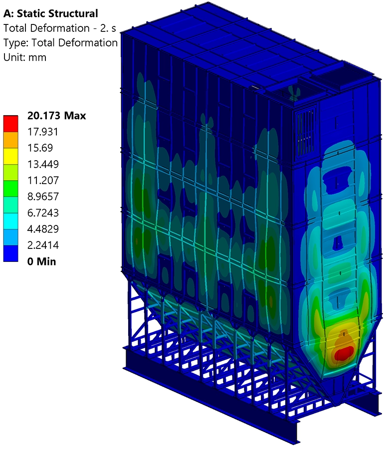
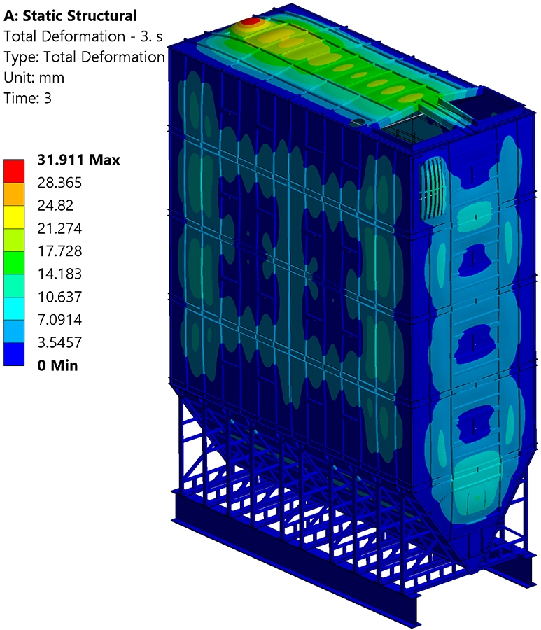
The maximum deformations for the three load combinations were 0.8 mm (self-weight only), 20 mm (self-weight + hydrostatic pressure) and 32 mm (self-weight + explosion overpressure). The largest deformation occurs at the roof panels under the explosion load, which is acceptable for an accidental load case. The silo meets all stiffness requirements.
Strength
Under load combination 1 (self-weight only), all Von Mises stresses remained well below the 187 MPa allowable limit for SS304, confirming low utilisation under dead load alone.
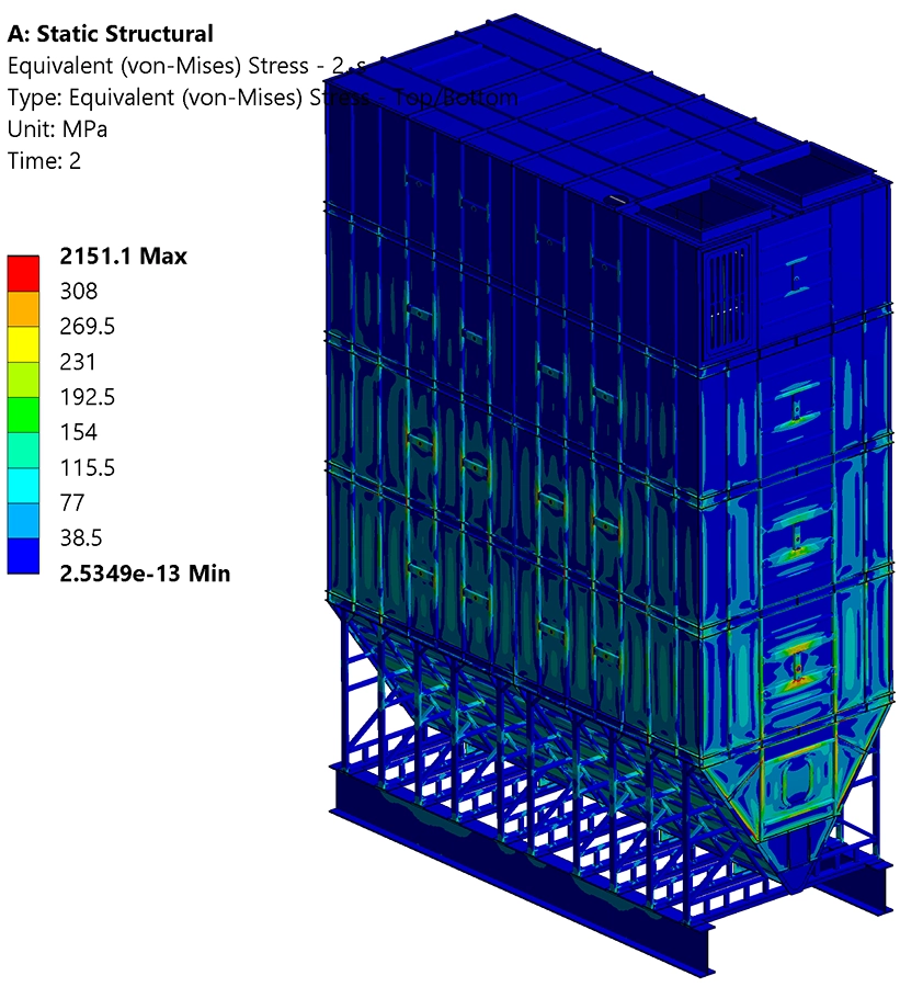
Under load combinations 2 and 3, localised stress peaks exceeded the allowable limits for both materials. However, isosurface visualisations demonstrated that these exceedances occurred exclusively at sharp geometric transitions and contact points between components — locations where stress singularities are inherent to the finite element method. Away from these singularities, the stress field remained within the allowable limits throughout the entire structure.
Tie rod verification
The twelve M16 tie rods (grade 8.8) that connect opposing walls were verified analytically per Eurocode EN 1993-1-8. The design tensile resistance of each tie rod was calculated at 90.4 kN, which comfortably exceeds the maximum applied tensile force of 43.2 kN. All tie rods pass the strength check.
Value Delivered
This nonlinear Finite Element Analysis provided the client with a comprehensive and documented strength and stiffness verification of the 40-tonne flour silo, fully compliant with the applicable Eurocode standards. The analysis not only confirmed that the final design meets all structural requirements, but also identified and resolved critical weak points before fabrication.
The recommended design modifications — upsized profiles, additional trough consoles and the tie rod arrangement — were validated through the FEA and incorporated directly into the production drawings. By investing in simulation-driven design verification upfront, the client avoided the risk of costly rework or on-site failures and gained the documented evidence required for third-party review and CE marking.
Need a structural verification for your silo or vessel?
Whether you are designing a silo, tank, pressure vessel or any other welded steel structure, our FEA and strength calculation services can help you verify your design to code. Get in touch for a free initial consultation.
Contact us or call us at +32 478 618 118