Finite Element Analysis (FEA)
Understanding how your product or structure will behave under real-world conditions is essential — but testing every scenario physically is expensive, slow and often impractical. Finite Element Analysis (FEA) lets you simulate the mechanical, dynamic and thermal response of complex designs with high accuracy, long before a prototype is built. At Quadco Engineering we use FEA to help engineers identify problems early, reduce prototyping cycles and develop lighter, stronger and more durable products.
What FEA can do for your design
The Finite Element Method divides your component or assembly into thousands of small elements, each with well-defined mechanical behaviour. By solving these elements together, FEA captures the response of the entire structure — including effects that hand calculations and simplified analytical formulas cannot reliably predict.
This makes FEA the right tool whenever your design involves complex geometry, nonlinear material behaviour, intricate load paths or a combination of all three. A single FEA model can provide detailed information on stress distributions, deformations, natural frequencies, stability limits and much more — enabling you to make well-informed design decisions with confidence.
Static and nonlinear analysis
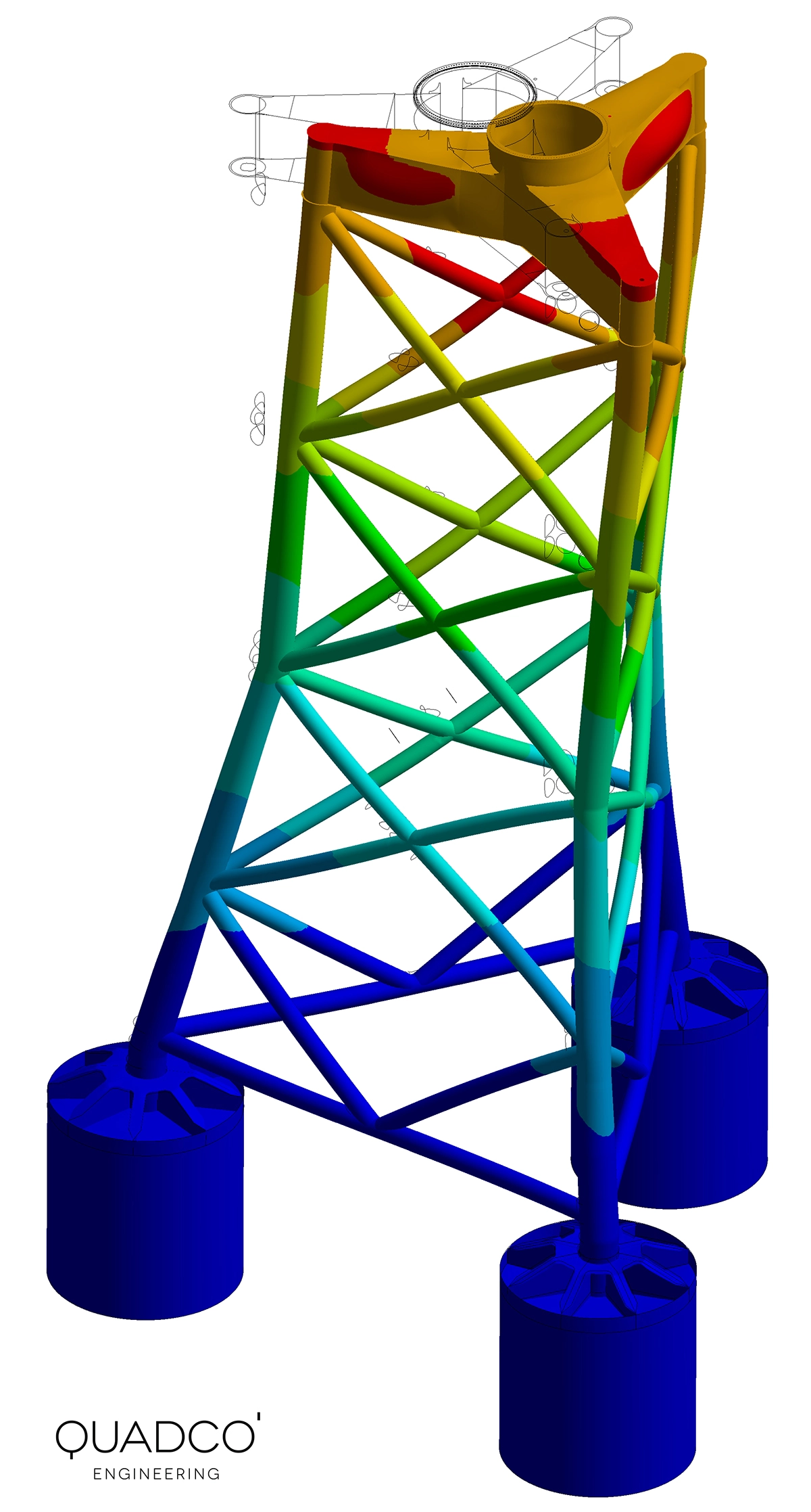
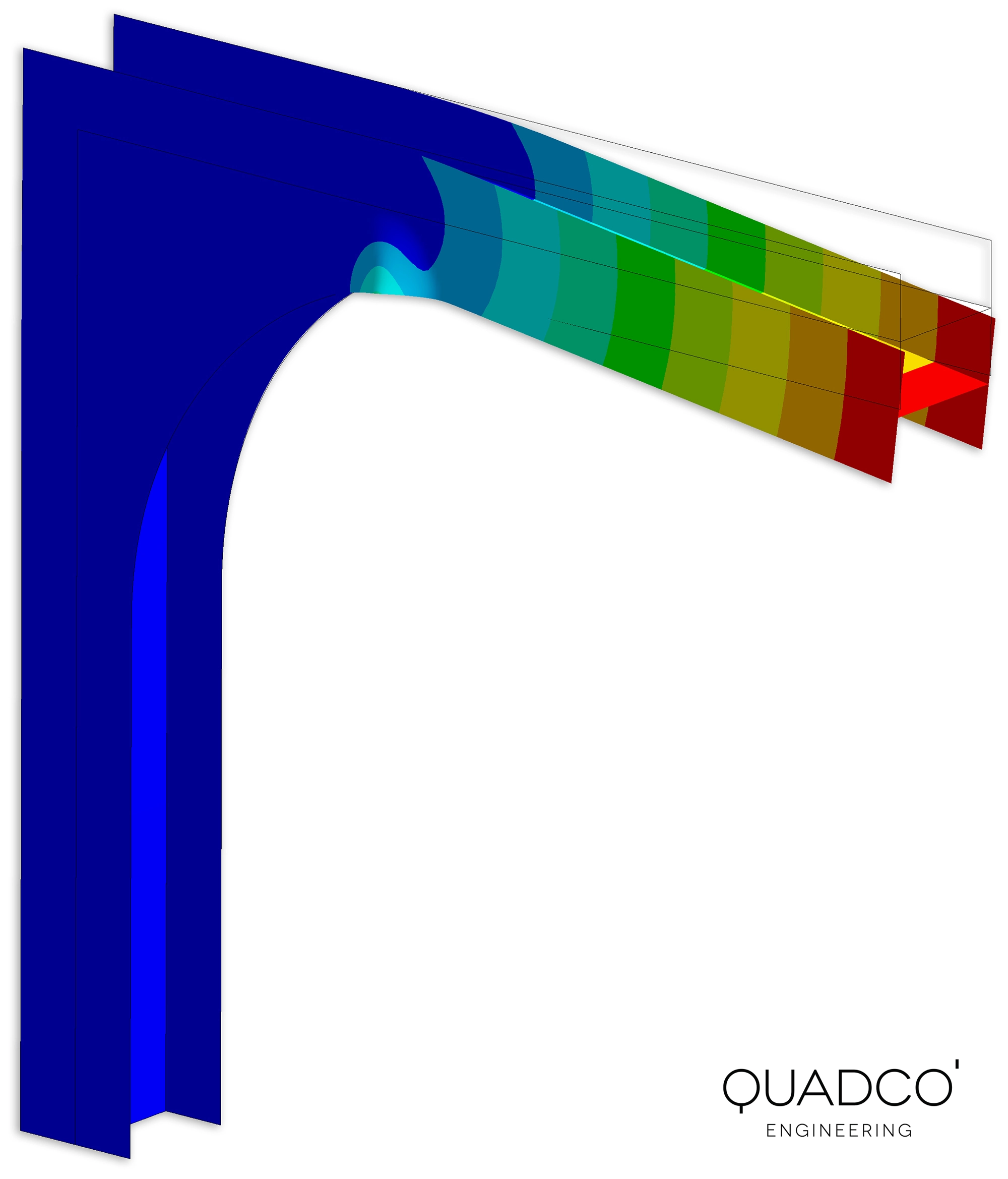
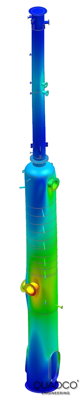
Static FEA determines stresses and deformations under loads that do not vary with time. For many engineering applications this is the starting point: verifying that a structure can carry its service loads without exceeding allowable stress limits or deforming beyond acceptable tolerances.
When the response becomes more complex — large deformations, material plasticity, contact between parts, bolted or welded joints — nonlinear FEA is required. We routinely handle advanced contact problems, plastic deformation, creep at elevated temperatures and post-buckling behaviour, giving you a realistic picture of how your design performs under demanding conditions.

Dynamic and vibration analysis
Many structures are exposed to time-varying loads: wind gusts, rotating machinery, traffic, seismic events or shock impacts. If the loading frequency approaches a natural frequency of the structure, resonance can amplify displacements and stresses to dangerous levels.
We perform the full range of dynamic FEA: modal analysis to identify natural frequencies and mode shapes, harmonic response analysis to evaluate behaviour under periodic loading, response spectrum analysis for seismic qualification, random vibration analysis for transport and operational environments, and explicit dynamic simulations for impact and drop-test scenarios.
Buckling and stability analysis
Slender structures under compressive or shear loading are susceptible to buckling: a sudden, uncontrolled loss of stability that can lead to catastrophic failure. Linear eigenvalue buckling analysis provides a quick first estimate of the critical load, but real-world imperfections often reduce the buckling capacity significantly.
We perform nonlinear buckling analyses that account for geometric imperfections, material plasticity and large deformations, following industry standards such as DNV-RP-C208 and Eurocode 3. This gives you a realistic and safe assessment of the stability of your structure.
FEA of composite materials
Composite materials offer an outstanding strength-to-weight ratio, corrosion resistance, high fatigue strength and the ability to tailor material properties to your specific loading conditions. At the same time, their layered, anisotropic nature makes them far more complex to analyse than metals.
We have extensive experience with the FEA of composite laminates. A composite structure must be evaluated layer by layer, accounting for the individual properties, thickness and fibre orientation of each ply, as well as the behaviour of the core material and matrix. We calculate laminate stiffness (ABD matrices), predict failure using industry-standard criteria and assess delamination risk under both static and fatigue loading.
Composite failure criteria
Predicting when and how a composite will fail requires dedicated failure criteria. We apply a wide range of approaches depending on your application and the applicable standards:
- First Ply Failure and Last Ply Failure
- Tsai-Wu and Tsai-Hill
- Hashin
- Puck and Cuntze
- LaRC and Hoffman
- Maximum stress and maximum strain
For fatigue assessment of composites we apply criteria such as Hashin-Rotem, Norris, Franklin-Marin and others, depending on the material system and loading conditions.
Optimisation with FEA
FEA is ideally suited for efficiently evaluating a large number of design variants. By parameterising geometry, material choices or loading conditions, we can run automated what-if studies to find the best balance between competing objectives — such as minimising weight while meeting stiffness and strength targets.
We offer parametric optimisation, topology optimisation for finding the optimal material layout, and Six-Sigma optimisation to ensure robust designs that perform reliably even when manufacturing tolerances and material scatter are taken into account. This systematic approach can significantly reduce the number of required prototypes and accelerate your development cycle.
Impact, drop tests and explicit dynamics
High-speed events such as impacts, crashes, drop tests and blast loading require explicit dynamic FEA. Unlike conventional (implicit) FEA, explicit methods can handle extreme deformations, contact changes and material failure that occur in fractions of a second. We use these techniques to evaluate product robustness, protective packaging, crash structures and defence applications.
Need an FEA simulation for your project?
From a quick stress check on a single component to a full nonlinear analysis of a complex assembly — we scale our approach to match your needs and timeline.
Get in touch for a free initial consultation. We will discuss your project, recommend the right analysis approach and provide you with a clear proposal.
Contact us or call us at +32 478 618 118Want to strengthen your own FEA skills? Have a look at our Practical Introduction to the Finite Element Method course.
Frequently asked questions
Common questions about Finite Element Analysis and simulation services.