Heat Transfer Analysis
Overheating components, inefficient cooling or unexpected thermal stresses can lead to product failures, costly redesigns and delayed time-to-market. With our heat transfer analysis services, you gain detailed insight into the thermal behaviour of your design — before committing to physical prototypes. Using Finite Element Analysis (FEA) and Computational Fluid Dynamics (CFD), we accurately predict temperature distributions, heat flows and thermal stresses so you can make confident engineering decisions.
Why thermal simulation matters
Temperature affects nearly every aspect of product performance. Materials weaken, electronics derate, seals degrade and tolerances shift — all because of heat. Yet thermal behaviour is notoriously difficult to estimate from hand calculations alone, especially when convection, radiation and conduction interact simultaneously.
A thermal simulation captures these complex interactions with high fidelity. It reveals hot spots you did not anticipate, quantifies safety margins, and lets you evaluate design changes in hours rather than weeks of testing. Whether you are developing a new product or troubleshooting field failures, simulation gives you the answers you need to move forward with confidence.
Thermal analysis with FEA
Finite Element Analysis is the method of choice when you need to understand how heat conducts through solid components and assemblies. We use FEA to calculate steady-state and transient temperature fields, accounting for conduction between parts, convective boundary conditions on surfaces and thermal radiation between components.
FEA-based thermal analysis is particularly effective when the convection coefficients are well characterised or can be reliably estimated. Typical applications include thermal stress assessment, predicting thermal expansion and distortion, evaluating cool-down and warm-up cycles, and identifying the risk of thermal shock in brittle materials like ceramics or glass.
Because the thermal results feed directly into a structural model, we can also calculate the stresses and deformations that arise from temperature gradients — a critical step for components operating at elevated temperatures or subjected to rapid thermal cycling.
Thermal analysis with CFD
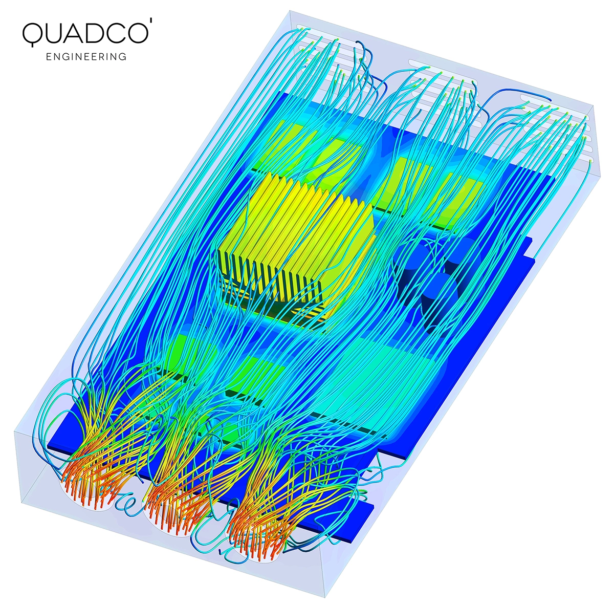
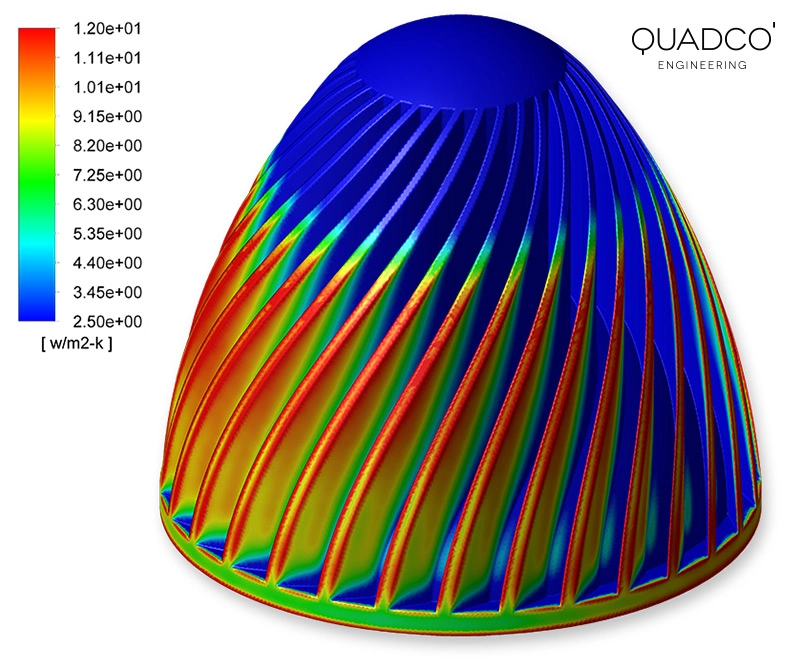
When the flow field has a significant impact on the heat transfer — or when the convection coefficient is unknown — Computational Fluid Dynamics is the right tool. CFD solves the full fluid flow equations together with the energy equation, which means the convective heat transfer coefficient is not assumed but calculated from first principles.
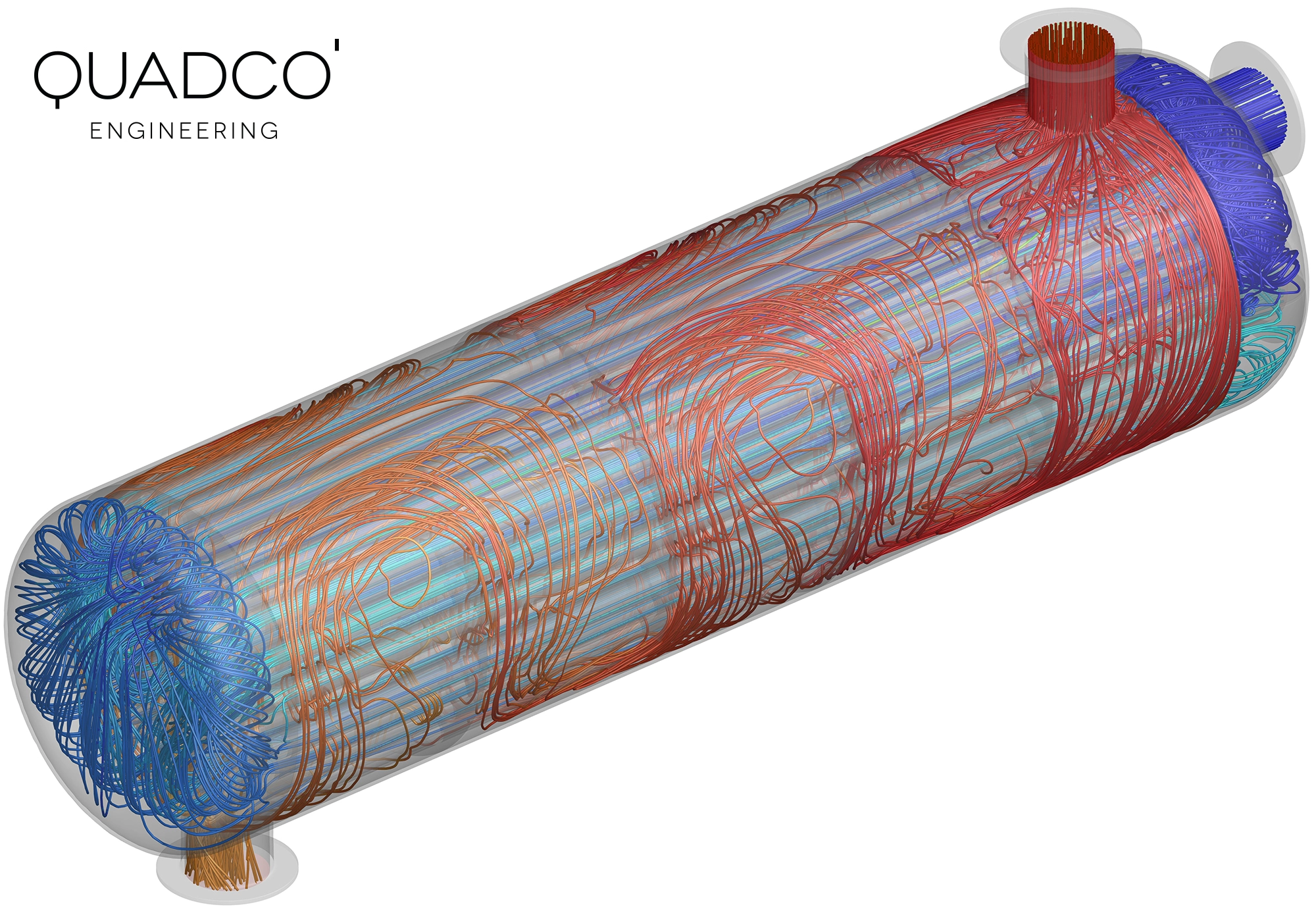
This makes CFD indispensable for applications such as electronics cooling, where complex airflow paths around PCBs and heat sinks determine component temperatures. It is equally important for heat exchanger design, HVAC systems, underhood thermal management in vehicles and industrial drying processes, where local flow velocities, turbulence and temperature-dependent fluid properties all affect the rate of heat transfer.
CFD also handles phase-change phenomena such as condensation, evaporation, melting and solidification — processes that are virtually impossible to capture with FEA or analytical methods alone.
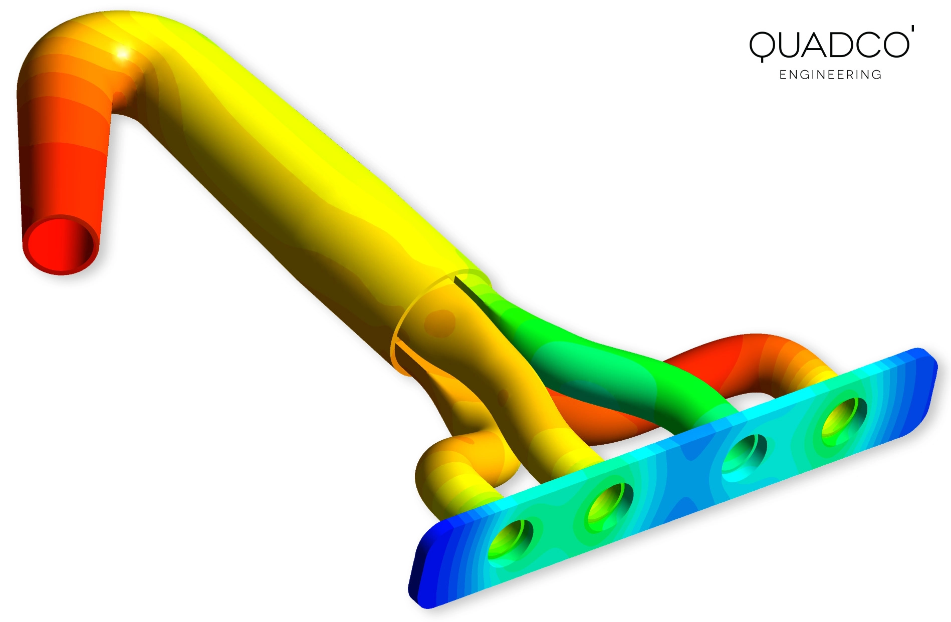
Conjugate heat transfer and Fluid-Structure Interaction
Many real-world thermal problems involve the simultaneous interaction of fluid flow, heat transfer and structural response. A hot fluid flowing through a pipe heats the pipe wall, which expands and generates thermal stresses. A cooled turbine blade deforms under combined thermal and mechanical loads, changing the flow path around it.
We handle these coupled problems through conjugate heat transfer analysis (simultaneous solving of fluid and solid thermal fields) and Fluid-Structure Interaction (FSI), where CFD and FEA solvers exchange temperature, pressure and displacement data. This approach delivers the most accurate results for thermally loaded structures operating in contact with flowing media.
Industries and applications
Our heat transfer analysis services support engineers across a wide range of industries. From consumer electronics to heavy industry, we have the experience and tools to tackle your thermal challenges:
- Electronics & semiconductors — thermal management of PCBs, power modules, LED lighting and data centre cooling
- Automotive & transport — underhood cooling, battery thermal management for EVs, exhaust system analysis and brake cooling
- Energy & renewables — solar thermal collectors, heat recovery systems, fuel cells and power generation equipment
- Process & chemical industry — heat exchangers, reactors, drying processes and HVAC design
- Industrial equipment — thermal shock assessment, furnace design, cooling strategy optimisation and thermal fatigue evaluation
Facing a thermal challenge? Let's talk.
Whether you need to validate a cooling concept, troubleshoot an overheating problem or optimise heat dissipation in a new design — our team of thermal simulation specialists is ready to help. We work with Ansys Mechanical, Ansys Fluent, Ansys CFX, Matlab and Python.
Get in touch for a free initial consultation. We will discuss your application, recommend the right analysis approach and provide you with a clear project proposal.
Contact us or call us at +32 478 618 118Frequently asked questions
Common questions about heat transfer analysis and thermal simulation.