The Challenge
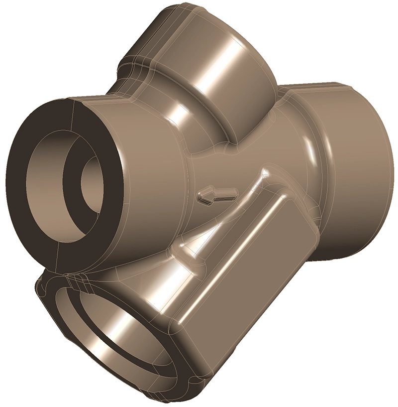
A manufacturer of steam system components needed to determine the maximum allowable internal pressure for a forged stainless steel fitting across a wide temperature range. The component — a complex multi-port pressure body designated V7630 — is manufactured from F316 stainless steel and operates at temperatures up to 620 °C.
Due to the component's non-standard geometry with multiple intersecting bores, threaded connections (M20 and M28), and varying wall thicknesses, a closed-form analytical calculation could not adequately capture the stress distribution. A Finite Element Analysis approach was required to account for the actual three-dimensional stress state, especially near geometric discontinuities where stress concentrations arise.
The analysis had to comply with ASME B31.1 (Power Piping) and deliver a clear pressure-temperature rating that the client could include in their product documentation.
Our Approach
We carried out a linear static FEA of the full 3D component in Ansys Mechanical. The analysis was structured to produce a complete pressure-temperature envelope in compliance with ASME B31.1.
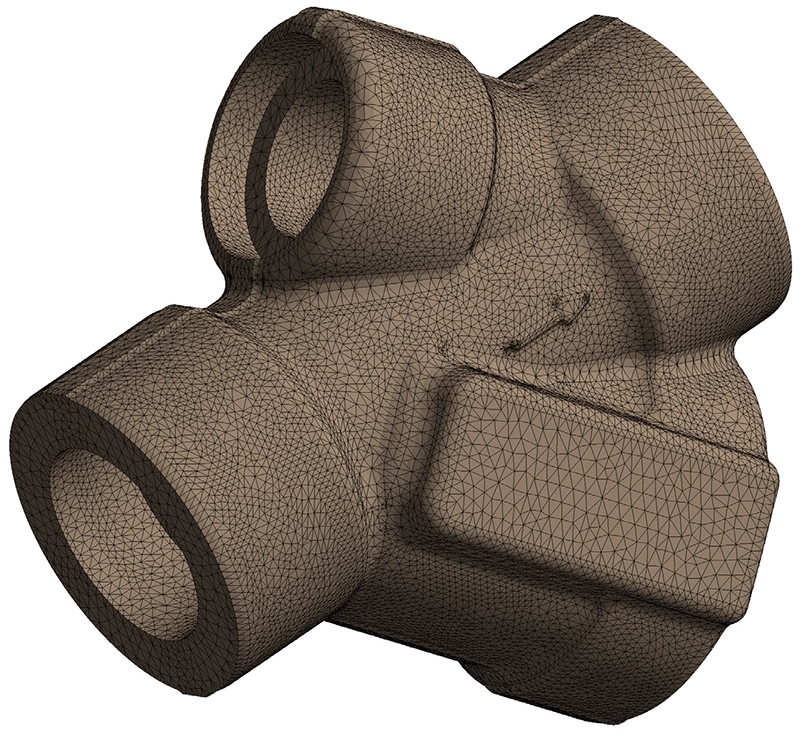
Geometry and meshing
The full component geometry was modelled including all internal bores, threaded holes and external features. The model was discretised using quadratic tetrahedral elements, with mesh refinement around the intersections and threaded regions where the highest stress gradients were expected.
Material properties per ASME B31.1
Temperature-dependent material properties for F316 were extracted from Table A-3 of ASME B31.1. At the reference analysis temperature of 400 °C, the key properties used were a modulus of elasticity of 169,000 MPa, a yield stress of 101 MPa, and a maximum allowable stress of 68 MPa (global) and 91 MPa (peak, corresponding to 90 % of yield).
Boundary conditions and loads
The component was constrained using the 3-2-1 method, which prevents rigid-body motion without introducing artificial reaction forces — an important requirement for a component in pressure equilibrium. An internal pressure of 12.2 MPa was applied to all internal surfaces, together with equivalent bolt forces on the M20 and M28 threaded connections, calculated as the product of the pressure and the respective bore area.
Stress assessment strategy
Because ASME B31.1 is primarily concerned with global (membrane) stresses rather than local peak stresses, the stress assessment was performed at two levels. First, the overall Von Mises stress distribution was evaluated against the global allowable stress. Second, at the location of the maximum stress concentration, a stress linearization was performed along a path through the wall thickness. This separated the total stress into its membrane, bending, and peak components, allowing the membrane-plus-bending stress to be checked against 90 % of the yield stress — a widely accepted criterion for local stress evaluation in pressure components.
Additionally, the shear stress at the bolt threads was calculated analytically and checked against 80 % of the ASME B31.1 allowable stress for all temperature levels.
Results
At the reference conditions of 12.2 MPa and 400 °C, the global Von Mises stress in the component body remained well below the allowable limit of 68 MPa, with a typical stress level of approximately 50 MPa. A localised stress hot spot of about 161 MPa was identified at a geometric discontinuity near a bore intersection. While this value exceeds the global allowable stress, it occurs over a very small volume and represents a peak stress that would be reduced by limited local plasticity in practice.
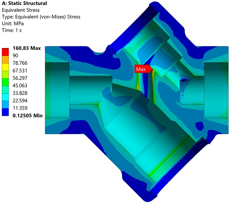
The stress linearization at the critical location confirmed that the membrane-plus-bending stress component remained just below the 91 MPa threshold (90 % of yield at 400 °C), validating the design at this pressure-temperature combination.
Because the FEA was linear, the results at 400 °C could be linearly scaled to other temperatures using the temperature-dependent allowable stresses from ASME B31.1. This produced a complete pressure-temperature rating curve covering the full operating range from 40 °C to 620 °C.
The shear stress check at the M20 and M28 bolt threads confirmed adequate margins at all temperatures. At the most severe condition (40 °C, 20.7 MPa), the calculated shear stresses of 27.6 MPa (M20) and 34.1 MPa (M28) remained well below the allowable shear stress of 91.5 MPa.
Value Delivered
By combining FEA simulation with the stress assessment methodology prescribed by ASME B31.1, we delivered a fully documented and code-compliant pressure-temperature rating for a component whose complex geometry precluded a purely analytical approach. The strength assessment included both global and linearized stress checks, as well as a shear stress verification at the threaded connections.
The client received a comprehensive analysis report suitable for inclusion in their product certification documentation, containing the complete pressure-temperature envelope, detailed stress contour plots, the linearized stress breakdown, and the thread shear stress verification. The clearly tabulated results enable the client to specify the maximum operating pressure for any temperature within the assessed range with full confidence in the ASME B31.1 compliance.
Need a pressure-temperature rating or code-compliant stress assessment?
Whether your project involves a strength verification to ASME, EN 13445 or another pressure equipment code, we can deliver the documented analysis you need. Get in touch for a free initial consultation.
Contact us or call us at +32 478 618 118