The Challenge
A fabricator of custom steel structures needed to verify that a large water sluice gate designed for a recreational water management facility in Belgium met all structural requirements before proceeding to fabrication. The gate — measuring 3.7 m in height and 1.5 m in width — is constructed from SS304 stainless steel and must withstand sustained hydrostatic pressure from a 3.5 m water column while also supporting lifting forces during operation.
Three specific structural criteria had to be satisfied in accordance with EN 1990 and EN 1991-1: the maximum deflection of the gate must not exceed 1/500th of its width (i.e. 3 mm), the peak equivalent stress must remain below the Eurocode allowable limit for SS304, and the structure must demonstrate adequate resistance against buckling under the applied hydrostatic loads.
Our Approach
We performed a comprehensive Finite Element Analysis in Ansys Mechanical, combining a nonlinear static analysis with a linear buckling assessment. The nonlinear formulation was essential to correctly capture both the geometric nonlinearity inherent in thin-plate deformations and the nonlinear frictional contact between the sluice gate and the surrounding concrete channel walls.
Geometry and mesh
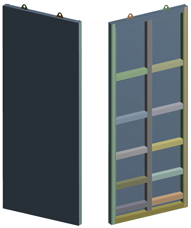
The gate assembly consists of square hollow sections (SHS) 100×100×8 mm welded to a 5 mm sealing plate, with two lifting lugs at the top for vertical hoisting. All plate and hollow-profile surfaces were converted to midsurfaces and discretised with 2D hexahedral shell elements. The mesh density was refined to ensure converged stress results throughout the critical regions of the structure.
Boundary conditions and contact
The gate is suspended from the two lifting lugs, which are constrained in the horizontal (X and Z) directions. At the bottom and sides, there is no fixed constraint — instead, frictional contact elements model the physical interaction between the gate edges and the concrete guide walls. This nonlinear contact formulation allows the gate to bear against the concrete under hydrostatic loading while remaining free to slide vertically during lifting operations.
Load cases and combinations
Three characteristic load cases were defined and combined into Ultimate Limit State (ULS) combinations per Eurocode:
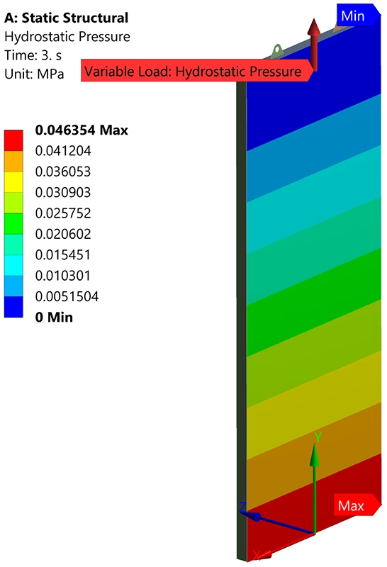
The first load case represents the self-weight of the structure. The second applies the full hydrostatic pressure distribution from a 3.5 m water column, resulting in a total horizontal force of approximately 90 kN. The third load case represents the lifting force required to raise the gate against friction under full hydrostatic loading — calculated at 27 kN based on a friction coefficient of 0.3. These were combined with appropriate partial safety factors (1.15 for permanent actions, 1.35 for hydrostatic pressure and 1.5 for the lifting load) into three ULS load combinations of increasing severity.
Results
Stiffness assessment
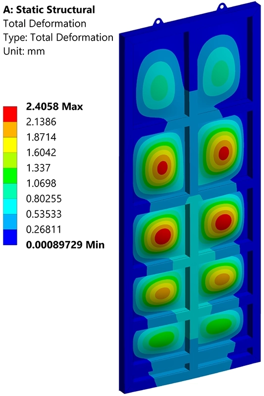
The maximum total deformation across all three load combinations was 2.41 mm, occurring under the combined self-weight and factored hydrostatic pressure (load combination 2). This is well below the 3 mm deflection limit (1/500th of the 1,500 mm gate width), confirming that the gate meets the stiffness requirement. Under self-weight alone, the maximum deformation was negligible at 0.06 mm.
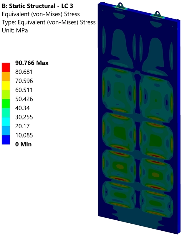
Strength assessment
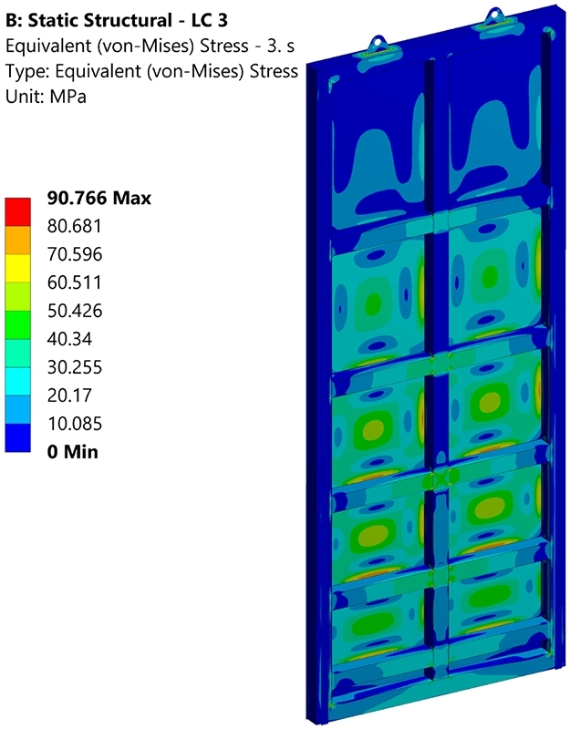
The peak Von Mises stress was 90.8 MPa, occurring under the most severe load combination 3 (self-weight + hydrostatic pressure + lifting load). The Eurocode allowable stress for SS304 is 187 MPa (yield strength of 215 MPa divided by a partial safety factor of 1.15), resulting in a utilisation ratio of approximately 49%. The structure therefore has a comfortable strength margin across all loading scenarios.
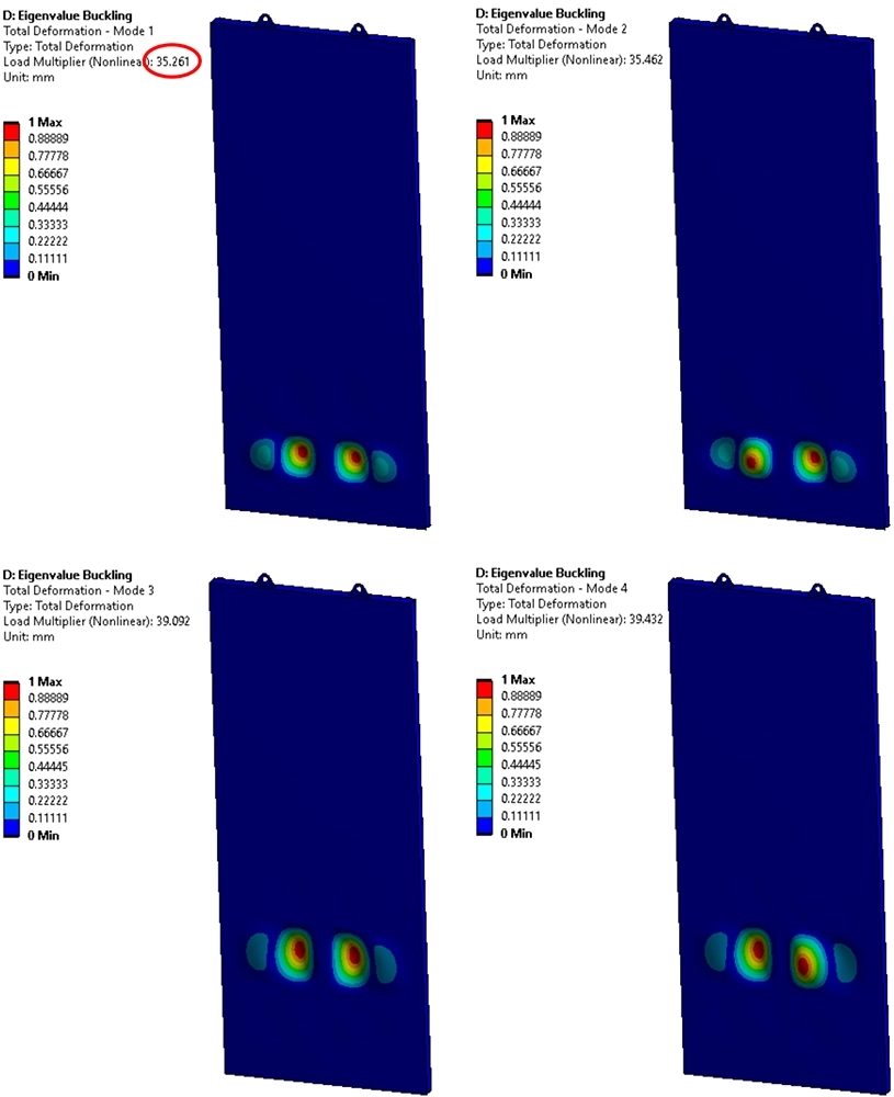
Buckling assessment
The linear eigenvalue buckling analysis demonstrated that the first buckling mode occurs at a load multiplier of 35 — meaning buckling would only initiate at 35 times the characteristic hydrostatic pressure. This exceptionally high safety margin against buckling confirms that the stiffening arrangement of the SHS profiles is highly effective at preventing plate instability under the applied loading conditions.
Value Delivered
By performing a nonlinear FEA with realistic contact conditions rather than relying on simplified hand calculations, we provided the fabricator with a rigorous, Eurocode-compliant verification of the sluice gate design across all three structural criteria: stiffness, strength and stability. The nonlinear contact model captured the actual load-transfer mechanism between the gate and the concrete channel — a critical detail that simplified approaches would either miss or handle too conservatively.
The analysis confirmed that the proposed design meets all Eurocode requirements with comfortable safety margins, enabling the fabricator to proceed directly to production without the need for design modifications. The results were delivered in a comprehensive technical report including deformation contour plots for all three load combinations, Von Mises stress distributions from both sides of the gate, the full eigenvalue buckling assessment with mode shape visualisations, and a clear summary table cross-referencing every result against its applicable limit.
For the gate operator, the analysis provided the documented structural evidence required for the facility's engineering safety file, demonstrating compliance with EN 1990 and EN 1991-1.
Need a structural verification for your steel or hydraulic structure?
Whether you require a Eurocode-compliant strength assessment, a nonlinear contact analysis, or a buckling and stability check, we can support your project from concept to sign-off. Get in touch for a free initial consultation.
Contact us or call us at +32 478 618 118