The Challenge
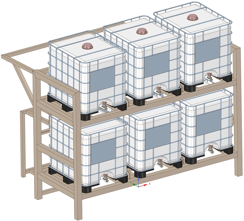
A process equipment manufacturer in Belgium needed an independent structural verification of a stainless steel support frame (skid) designed to carry six IBC tanks, each weighing 1,300 kg when fully loaded. The total payload of 7,800 kg placed significant demands on the welded frame, and the client required documented proof that the structure met the strength, stiffness and stability requirements of EN 1993-1-1 (Eurocode 3) and EN 1993-1-4 for stainless steel structures before releasing the design for fabrication.
The key questions were straightforward but critical: Would the SS304 stainless steel profiles remain below their allowable stress limit under the factored load combination? Would deflections stay within the serviceability limits defined by Belgian standard NBN B 03-003? And would the structure be safe against buckling?
Our Approach
We performed a full finite element analysis of the skid in Ansys Mechanical, combining a static stress analysis with a linear eigenvalue buckling analysis. The entire workflow was structured around the Eurocode load combination framework to produce results that could be directly assessed against the code limits.
Shell element model
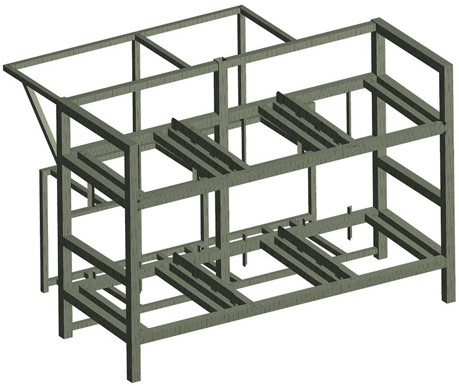
The hot-rolled SS304 (EN 1.4301) profiles were discretised with linear 2D shell elements, which are ideally suited for accurately capturing bending, membrane and shear behaviour in thin-walled sections. Shell elements provide an efficient yet precise representation of the structural response without the computational overhead of a full solid model. A refined mesh was applied at joints and connection points to ensure accurate stress recovery in these critical areas.
Loading and boundary conditions
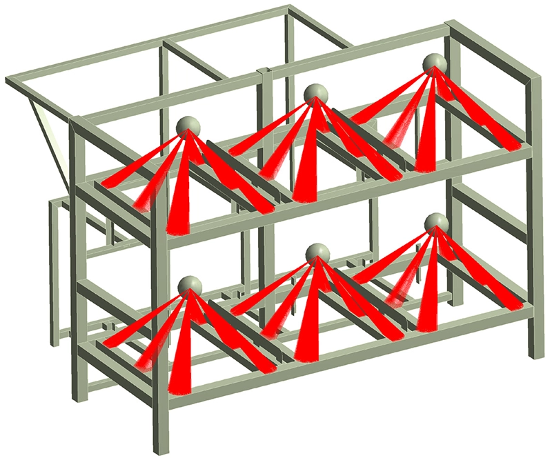
The structure was fully restrained at nine support points, each constrained in all six degrees of freedom. Two load cases were defined: the self-weight of the steel frame, and the weight of the six tanks. The tank masses were modelled as point masses of 1,300 kg each, coupled to the frame via flexible link elements that transfer gravitational forces without introducing artificial stiffness into the model. Both loads were combined under a single Eurocode ultimate limit state combination with a partial safety factor of 1.35.
Design iteration
An initial analysis revealed that several L100×100×4 mm angle profiles exceeded the allowable stress of 191 MPa (fy / γM = 220 / 1.15). We recommended increasing the wall thickness from 4 to 6 mm on four specific profiles. The final results presented below are based on the updated design with these modifications incorporated.
Results
Deflection assessment
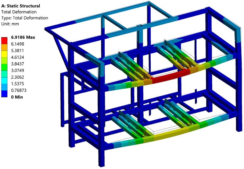
The maximum vertical deflection of 6.9 mm occurred in the upper horizontal beam, a span of 3,425 mm. This corresponds to a relative deflection of approximately L/500. The serviceability limit for a non-cantilevered platform beam according to NBN B 03-003 (Table 4, item 17) is L/300. The structure therefore comfortably satisfies the stiffness requirement.
Stress assessment
The Von Mises equivalent stress remained globally below the allowable limit of 191 MPa throughout the structure. Localised stress concentrations exceeding this value were observed at four corner junctions of the horizontal beams. These peaks are the result of numerical singularities — an inherent characteristic of shell models at sharp profile intersections — and do not represent physically meaningful stresses. With the wall thickness modification applied, the structure fully satisfies the strength requirements of Eurocode 3.

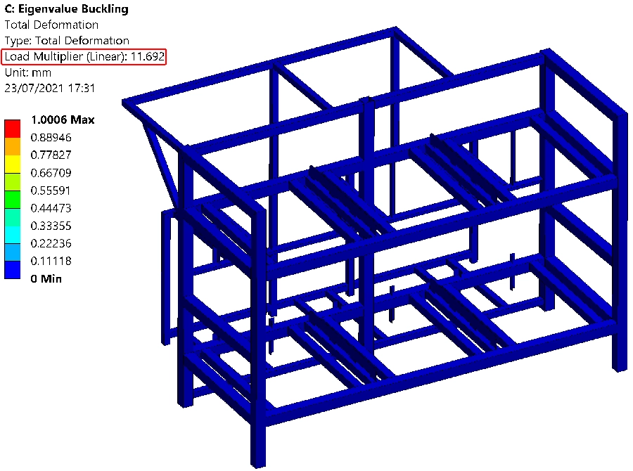
Buckling stability
A linear eigenvalue buckling analysis confirmed that the critical buckling load factor is 11.7, meaning the structure can carry nearly 12 times the applied load before a buckling mode is triggered. According to Eurocode, when the critical load factor exceeds 10, no further nonlinear buckling assessment is required. The structure is therefore amply stable.
Value Delivered
This project delivered a fully documented FEA verification report demonstrating compliance with Eurocode 3 across all three assessment criteria: strength, serviceability and stability. Beyond a simple pass/fail verdict, the analysis identified specific profiles that required reinforcement and provided the client with a concrete, actionable design modification — increasing wall thickness from 4 to 6 mm on four angle profiles — before any material was cut or welded.
By catching this issue at the design stage through simulation, the client avoided costly rework during fabrication. The report, complete with deformation plots, stress contours and buckling mode shapes, served as the structural evidence required for client approval and formed part of the project's technical documentation package.
Need a structural verification for your steel frame or support structure?
Whether it involves a Eurocode strength check, a buckling stability assessment or a full FEA verification, we deliver documented, code-compliant results you can rely on. Get in touch for a free initial consultation.
Contact us or call us at +32 478 618 118