The Challenge
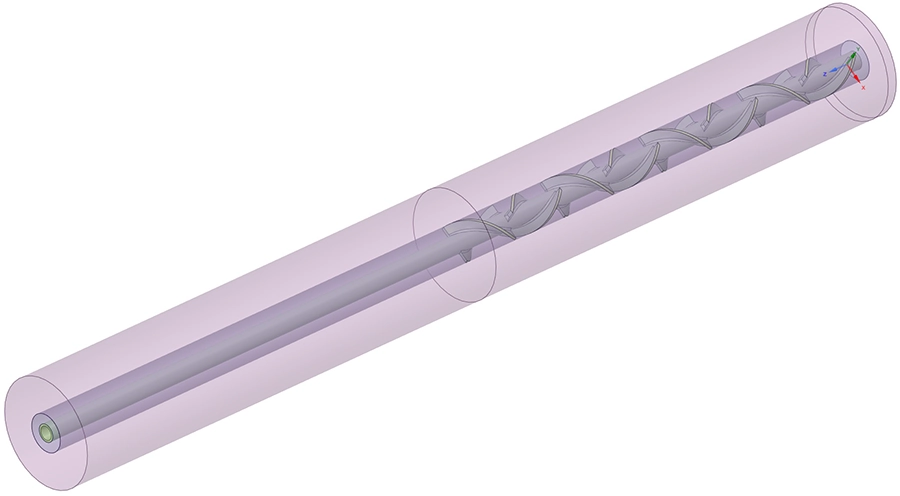
A chemical processing company required an in-depth understanding of the flow behaviour and heat transfer performance inside a compact tubular reactor. The reactor, measuring 240 mm in length with a 20 mm inner diameter, contains a helical static mixer screw and a centrally placed thermocouple. The screw induces a whirling flow path that promotes mixing of the process fluid as it travels through the heated tube.
The client needed to validate the internal flow patterns and velocities, and determine how effectively the reactor transfers heat from the externally heated wall to the fluid under different operating conditions. Four scenarios were defined, combining two volume flow rates (6 ml/min and 19 ml/min) with two fluid viscosity values (0.3 mPa·s and 1 mPa·s). Understanding the interplay between flow rate, viscosity and heat transfer is essential for optimising the reactor's performance and scale-up potential.
Our Approach
We built a full 3D conjugate heat transfer model of the reactor in Ansys Fluent, including both the fluid domain and the solid components: the Inconel 625 outer tube and the S316L stainless steel helical screw. A conjugate heat transfer approach was essential because the thermal interaction between the heated tube wall, the metallic screw and the flowing fluid determines the actual temperature distribution inside the reactor.
Temperature-dependent fluid properties
The process fluid exhibits strongly temperature-dependent thermal properties. Between 60 °C and 600 °C, the density drops from 1,002 kg/m3 to 504 kg/m3, while the heat capacity nearly doubles from 1,678 J/kg·K to 3,497 J/kg·K. The thermal conductivity decreases by more than half over the same range. Each property was implemented as a polynomial fit derived from measured data points, ensuring the simulation faithfully captures how the fluid's behaviour changes as it heats up along the reactor length.
Calibrating the heat input against measurements
The reactor is heated by a 2,300 W thermal radiator surrounding the tube. However, due to the low emissivity of Inconel 625 (below 0.1) and unknown heat losses to the environment, only a fraction of this power reaches the fluid. The client provided a measured fluid temperature of 510 °C at 200 mm from the inlet for the 6 ml/min case with a 200 °C inlet temperature. Using an energy balance, the actual heat absorbed by the fluid was estimated at approximately 73 W — just 3% of the radiator's rated power. We tuned the applied heat load on the tube wall to 96.6 W to match this measurement point, then applied the same heat load to all four scenarios for a consistent comparison.
Laminar steady-state solver
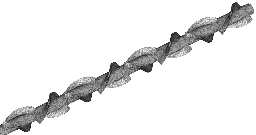
Given the very low flow rates and small tube diameter, the Reynolds numbers in all scenarios are well below the turbulent transition threshold. A steady-state laminar solver was therefore appropriate, avoiding unnecessary computational cost while maintaining accuracy. The polyhedral mesh was refined around the helical screw surfaces to capture the complex spiralling flow path and the thermal boundary layers on the screw and tube walls.
Results
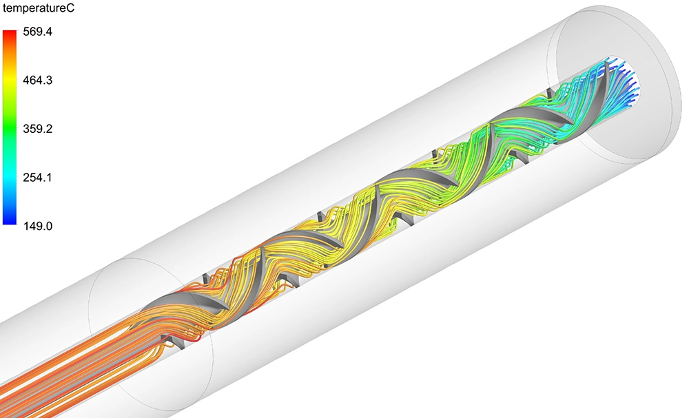
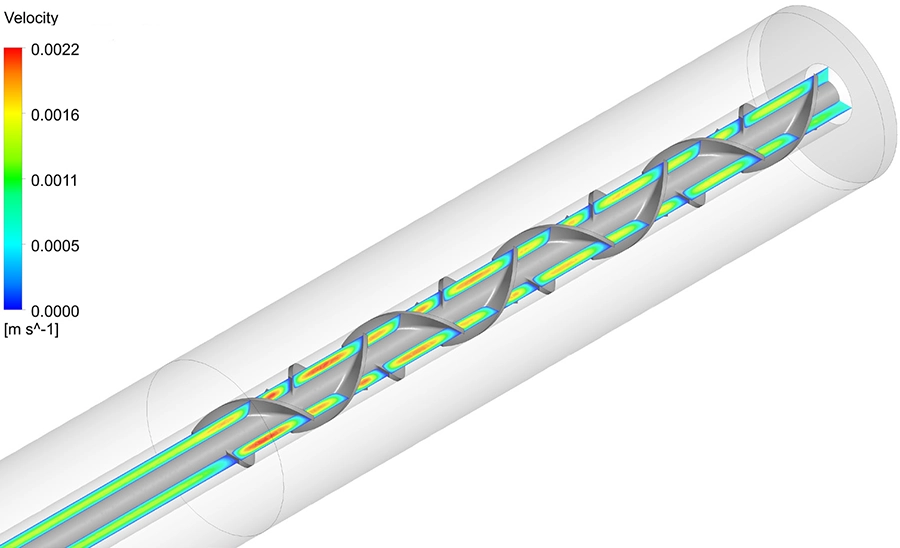
The streamline visualisations confirmed that the helical screw successfully induces a well-defined whirling flow throughout the reactor, with no significant dead zones or flow stagnation regions. The spiralling motion brings the fluid into repeated contact with the heated tube wall, which is exactly the mixing behaviour the static mixer is designed to achieve.
Effect of flow rate on outlet temperature
As expected, the flow rate has a decisive impact on the outlet temperature. At the lower flow rate of 6 ml/min, the fluid has more residence time in the heated zone, reaching an average outlet temperature of approximately 531 °C — well above the 510 °C measured at the 200 mm position. At the higher flow rate of 19 ml/min, the shorter residence time limits heating to an average outlet temperature of about 323 °C. Despite this temperature difference, the total heat absorbed by the fluid is marginally higher at the higher flow rate (approximately 81 W versus 80 W), indicating slightly improved convective heat transfer at the increased velocity.
Effect of viscosity on heat transfer
One of the most significant findings was that fluid viscosity has virtually no effect on the heat transfer efficiency. The temperature profiles and absorbed heat values were nearly identical between the 0.3 mPa·s and 1 mPa·s cases at the same flow rate. Viscosity primarily affects the pressure drop across the reactor and therefore the pumping power required, but both values remain very small and negligible in the overall energy balance.
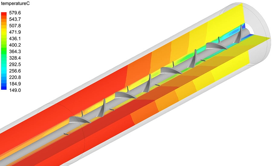
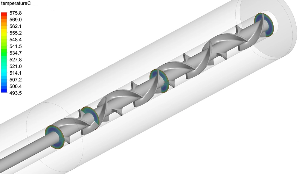
The cross-sectional temperature plots at 0, 120, 200 and 240 mm from the reactor inlet revealed how the thermal field evolves along the reactor length. At the inlet, a strong radial temperature gradient exists between the hot tube wall and the cooler core flow. By the outlet, the static mixer has redistributed the heat across the cross-section, significantly reducing the radial non-uniformity. This confirms that the helical screw is effective at promoting radial heat transport, a critical factor for achieving consistent product quality in chemical processing applications.
Value Delivered
This CFD analysis provided the client with validated, quantitative insight into the reactor's thermal-hydraulic performance across the full operating envelope. The calibrated model, anchored to a physical temperature measurement, gives confidence that the predicted temperatures and flow patterns are representative of real-world conditions.
The key finding that viscosity does not influence heat transfer efficiency simplifies the client's process design: they can adjust fluid viscosity to suit other process requirements without impacting the reactor's thermal performance. The detailed streamline and contour visualisations provide a clear understanding of the mixing quality achieved by the helical screw, which is directly relevant for future design optimisation — for example, adjusting the screw pitch, reactor length or heating power for different target temperatures and throughputs.
By combining CFD flow simulation with conjugate heat transfer analysis, we delivered a comprehensive performance characterisation in a single simulation campaign — a far more efficient and informative approach than iterative physical prototyping and testing.
Need to validate or optimise a reactor, mixer or process equipment?
From flow analysis and thermal performance prediction to design optimisation, we help engineers quantify performance before committing to production. Get in touch for a free initial consultation.
Contact us or call us at +32 478 618 118