The Challenge
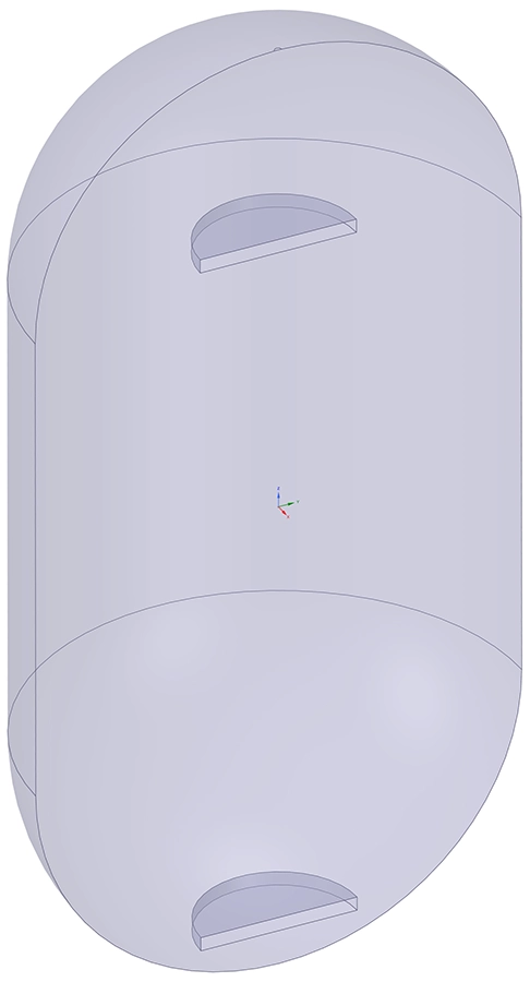
A large-scale thermal buffer tank (heat accumulator tank) was being designed as part of a district heating network in the Netherlands. The pressurised cylindrical tank, 14 m in internal diameter with semi-spherical ends, stores approximately 2,920 m3 of water at an operating pressure of 1.99 bar. Hot water at 120 °C and cold water at 70 °C are fed in and extracted through two circular diffusors (Ø 4.5 m, height 0.4 m) positioned near the top and bottom of the tank respectively.
The core engineering question was whether the thermocline — the thin transition zone separating the hot and cold water layers — would remain stable during charging and discharging at a volume flow rate of 634 m3/h. A particular concern was the proximity of the lower diffusor to the curved tank wall: the flow might cause a Coanda effect, generating large-scale vortices that could disrupt the thermal stratification and degrade the tank's storage efficiency.
Our Approach
We modelled the full fluid domain of the tank in Ansys Fluent using a half-symmetry model to keep the transient computation times manageable. The mesh consisted of polyhedral elements with inflation layers along the tank walls and diffusor surfaces to resolve near-wall flow behaviour accurately. A density-based solver was selected to properly capture the buoyancy-driven flows arising from the temperature-dependent density differences across the thermocline.
Phase 1 — Diffusor position study
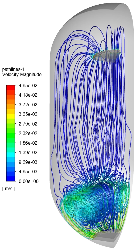
In the first phase, steady-state analyses compared two positions for the lower diffusor: the original design at 628 mm from the tank wall, and an alternative at 300 mm. Both scenarios were run first with a uniform water temperature (no thermocline) and then with the actual temperature distribution in place, allowing us to isolate the effect of density differences on the flow pattern. Velocity contour plots and streamline visualisations were extracted to identify vortex structures and the Coanda effect.
Phase 2 — Transient thermocline behaviour
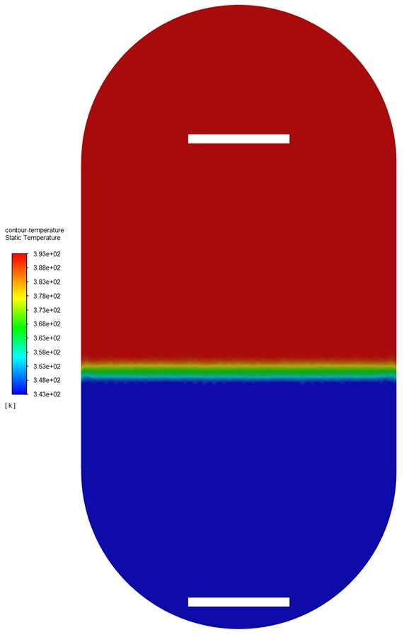
The second phase focused on the dynamic behaviour of the thermocline itself. Fully transient conjugate thermal analyses were performed for two operating scenarios: cold in (cold water fed through the bottom diffusor, hot water extracted at the top) and warm in (hot water fed through the top diffusor, cold water extracted at the bottom). The initial thermocline thickness was set to 0.8 m, defined as the zone where the temperature deviates by more than 1% from the bulk hot or cold temperatures. 80 monitoring points distributed vertically between the diffusors tracked the temperature profile over time.
Simulation duration
Each transient analysis ran until the thermocline reached the opposite diffusor — approximately 8,800 seconds for the cold-in scenario and 7,800 seconds for warm-in, corresponding to one full volume exchange between the diffusors.
Results
Diffusor positioning has minimal impact
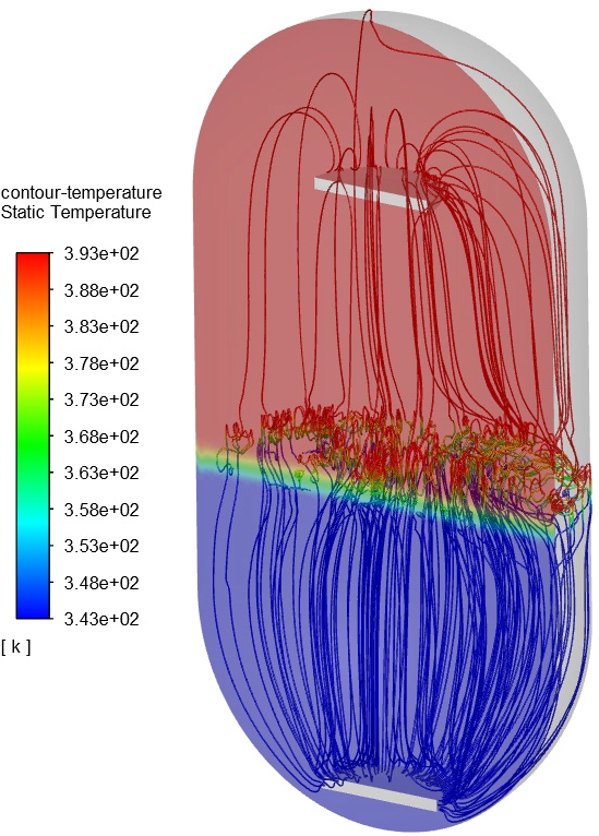
The steady-state analyses with uniform water temperature revealed large-scale vortices spanning the entire tank for both diffusor positions, driven by the Coanda effect along the curved bottom wall. However, when the actual temperature distribution was applied (without solving the energy equation, so the thermocline remained fixed), the flow pattern changed dramatically: the density gradient across the thermocline acted as a natural barrier, confining the vortices to the lower section well below the stratification zone. The difference between the 628 mm and 300 mm configurations was negligible — both produced near-identical flow confinement.
The thermocline remains stable
The fully transient analyses confirmed that the thermocline remained intact throughout both charging scenarios. The large vortices observed in the steady-state solutions disappeared entirely in the transient simulations — an important finding that underscored the limitations of steady-state assumptions for this type of dynamic thermal storage problem. In reality the thermocline moves continuously, and a steady-state approach, which assumes a stationary flow field, overestimates the strength of recirculation.
In the cold-in scenario the thermocline thickness grew gradually from 0.8 m to approximately 2 m over the full cycle of 8,800 s. In the warm-in scenario the growth was slightly larger, reaching about 2.5 m over 7,800 s. This more rapid thickening occurred when the thermocline entered the semi-spherical end cap at the bottom of the tank, where the decreasing cross-sectional area laterally compressed the transition zone.
Value Delivered
This project demonstrated the critical importance of choosing the right simulation approach. A steady-state CFD analysis alone would have predicted problematic large-scale vortices throughout the tank — potentially leading to unnecessary and costly design modifications. The transient simulation told a fundamentally different and far more realistic story: the density-driven stratification creates a natural cushioning effect that suppresses mixing and keeps the thermocline intact.
The engineering team received clear, quantitative evidence that the original diffusor positioning was acceptable. The analysis showed that no geometric redesign of the lower diffusor was required, the thermal stratification remains stable under both charging and discharging operating modes, the semi-spherical tank geometry causes some additional thermocline thickening — a predictable effect that can be accounted for in the operational control strategy, and the transient animated visualisations provided an effective communication tool for project stakeholders unfamiliar with CFD.
By combining computational fluid dynamics with thermal analysis, we delivered the confidence needed to proceed with the buffer tank design without modification, saving the project both time and budget.
Designing a thermal energy storage system?
Whether you need to validate a buffer tank design, analyse thermocline behaviour, or optimise diffusor configurations, we can help. Get in touch for a free initial consultation.
Contact us or call us at +32 478 618 118