The Challenge
A Belgian manufacturing company needed to redesign the cooling system for a large steel cooling plate used to cool aluminium moulds. The original design relied on a single serpentine cooling channel, which produced excessively high temperature gradients across the plate during the cooling cycle. These steep thermal gradients raised concerns about plate deformation, potentially leading to uneven contact with the mould and inconsistent product quality.
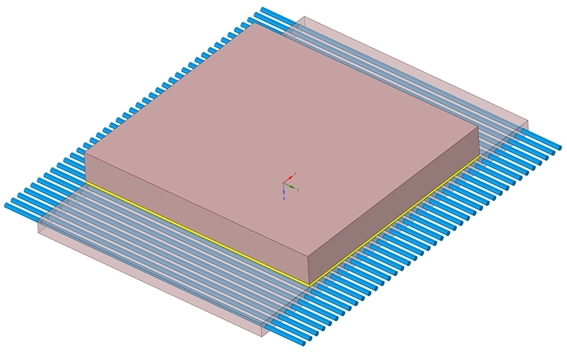
The redesigned cooling plate features 40 parallel channels (Ø 16 mm) fed by a collector, replacing the original single-channel layout. The goal was to determine the optimal coolant flow rate to bring the temperature gradient below an acceptable threshold while cooling the aluminium mould from 265 °C to 140 °C within the maximum allowable cooling time of 600 seconds.
Our Approach
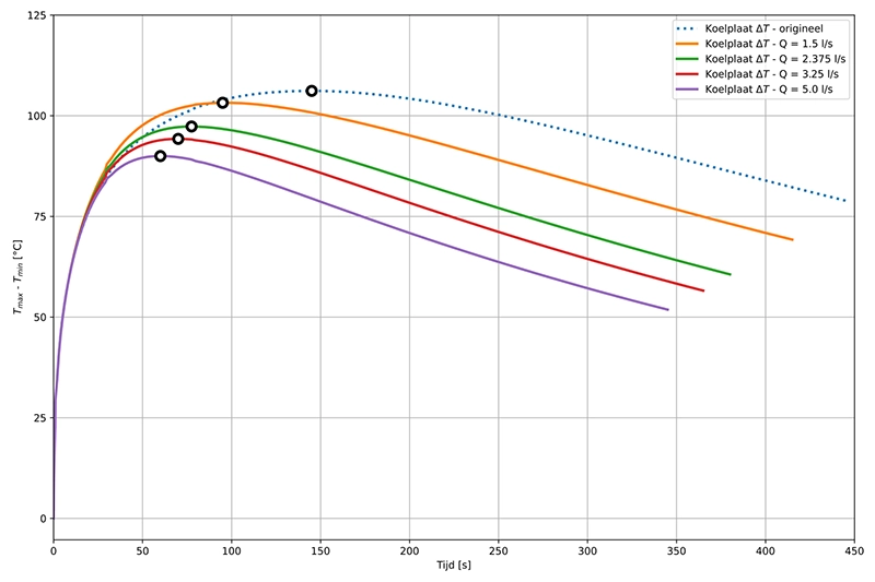
We performed a series of transient conjugate heat transfer (CHT) simulations in Ansys Fluent to model the coupled fluid flow and heat transfer between the cooling water, the steel plate and the aluminium mould. The analysis covered four coolant flow rates — 1.5, 2.375, 3.25 and 5 l/s — and compared all results against the original single-channel design.
Geometry & boundary conditions
The cooling plate measures 1,300 × 900 × 50 mm (S355 steel) and contains 40 drilled channels of 16 mm diameter. The mould (Al6082, 830 × 900 × 220 mm, 443 kg) sits on top of the plate with a thermal resistance layer modelled at the interface. Cooling water enters the channels at 20 °C, and all exposed surfaces exchange heat with the surroundings via natural convection at 20 °C.
Transient conjugate heat transfer
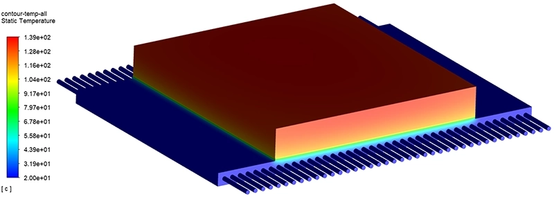
Each simulation started at the initial mould temperature of 265 °C and ran until the maximum mould temperature dropped below 140 °C. The transient solver captured the full time evolution of temperatures in the mould, the plate and the coolant — including the peak thermal gradients that occur early in the cooling cycle when the temperature difference between the hot mould and the cold water is at its maximum.
Parametric flow rate study
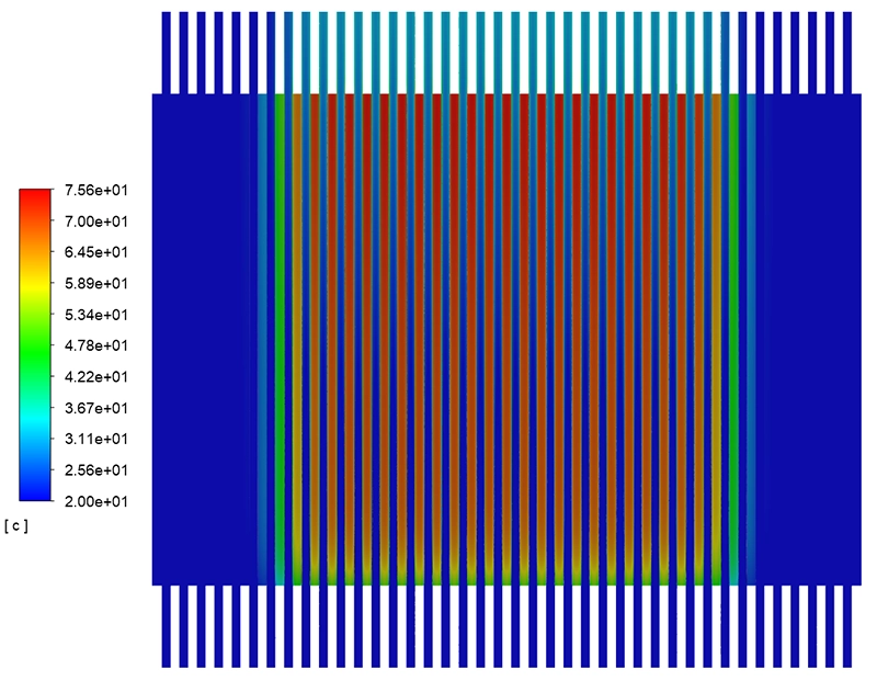
The four flow rates were chosen to span the practical operating range of the cooling system. For each case we tracked the mean and maximum mould temperature, the outlet water temperature rise, and — critically — the maximum temperature difference across the cooling plate, both through the full plate thickness and through the mid-plane cross-section containing the channel centrelines.
Results
All four flow rates achieved the target cooling time of under 600 seconds. At the highest flow rate of 5 l/s, the maximum mould temperature reached 140 °C in approximately 335 seconds — a reduction of nearly 100 seconds compared to the original design.
The key finding concerned the temperature gradients in the cooling plate. The 40-channel design dramatically reduced the mid-plane temperature difference compared to the original serpentine layout: from 77.0 °C down to 55.6 °C at 1.5 l/s and just 28.9 °C at 5 l/s. A quadratic fit of the mid-plane gradient as a function of flow rate was established, providing an engineering tool for interpolating between the analysed data points.
The outlet water temperature rise decreased with increasing flow rate, from approximately 10 °C at 1.5 l/s to 4.3 °C at 5 l/s. This confirms that higher flow rates extract heat more uniformly across all 40 channels, preventing localised hotspots in the downstream sections of the plate.
However, the analysis also showed that the originally targeted maximum gradient of 10 °C is difficult to achieve with this geometry, regardless of flow rate. Since the plate is in direct thermal contact with a 265 °C mould while the coolant enters at 20 °C, a through-thickness gradient is physically unavoidable during the early phase of the cooling cycle. The simulation results provide the quantitative evidence needed to set a realistic, achievable gradient target for the redesigned system.
Value Delivered
By combining CFD simulation with transient thermal analysis, we provided the client with a complete, quantitative comparison of the redesigned 40-channel cooling plate against the original single-channel design across four operating conditions. The study delivered clear evidence that the multi-channel layout substantially reduces thermal gradients and cooling times.
The parametric approach — covering four flow rates and including a curve-fit equation — gave the engineering team a practical tool to select the optimal operating point, balancing cooling performance against pump capacity and energy consumption. It also established a realistic performance envelope, preventing over-specification of the cooling system based on an unattainable 10 °C gradient target.
Need to optimise a cooling system or thermal design?
Whether you are designing cooling channels, evaluating heat exchanger performance or predicting thermal gradients, our CFD and thermal analysis expertise can help. Get in touch for a free initial consultation.
Contact us or call us at +32 478 618 118