The Challenge
An HVAC engineering firm in Belgium was designing the climate control system for a new arts center theater with a 181-seat retractable grandstand. Their central question: can the proposed ventilation layout keep the audience area below 26 °C during a fully occupied performance, and how long before that threshold is exceeded?
Theaters present a particularly demanding thermal challenge. A full audience generates substantial heat — in this case 18.1 kW from spectators alone — compounded by stage lighting (10 kW) and an orchestra pit (4 kW), totalling over 32 kW of internal heat gains. Fresh conditioned air is supplied through 52 floor-mounted displacement diffusers in the grandstand and six large wall-mounted grilles beneath the retractable tribune, delivering a combined 10,000 m3/h. The engineering firm needed to compare two alternative extraction layouts to determine which one provides the best thermal comfort for the audience.
Our Approach
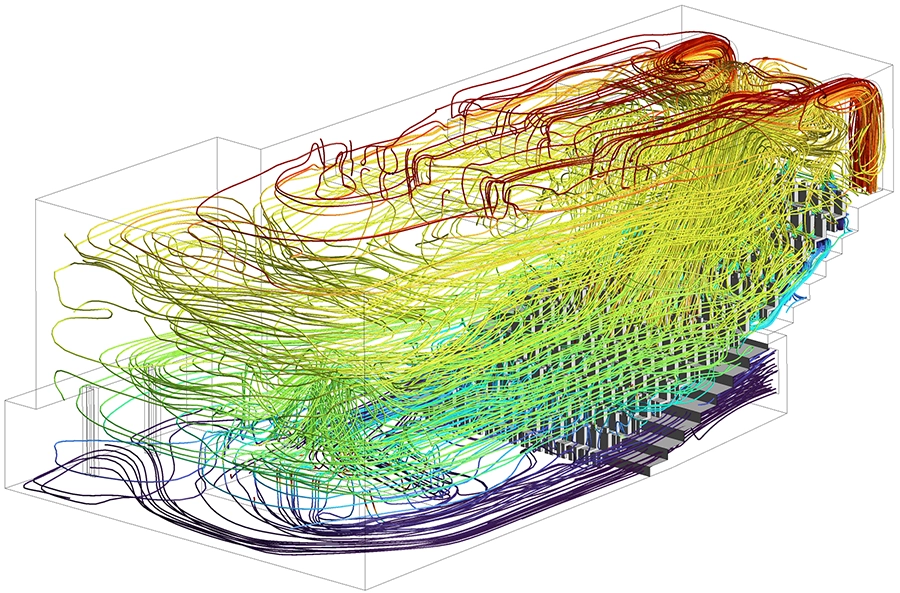
We built a detailed CFD model of the full theater air volume in Ansys Fluent, including every air inlet, the grandstand geometry, audience heat generation zones, orchestra pit, and two rows of ceiling-mounted stage lighting. The turbulent flow field was solved using the k-ω SST model with the energy equation enabled, and air density was modelled as temperature-dependent to capture buoyancy-driven flows accurately.
Comparing two extraction layouts
Two air extraction configurations were evaluated. In Option 1, warm air is extracted through a single large opening at the top of the rear wall. In Option 2, extraction occurs through two lateral ducts at the sides of the rear wall. For each layout we ran both steady-state and transient analyses to capture the full picture.
Steady-state thermal analysis
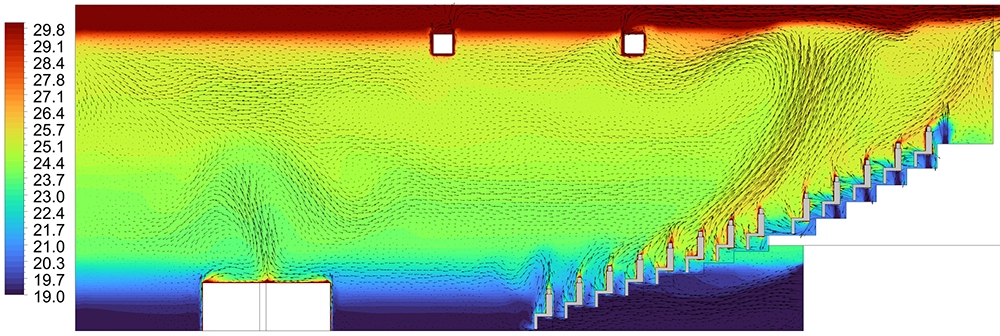
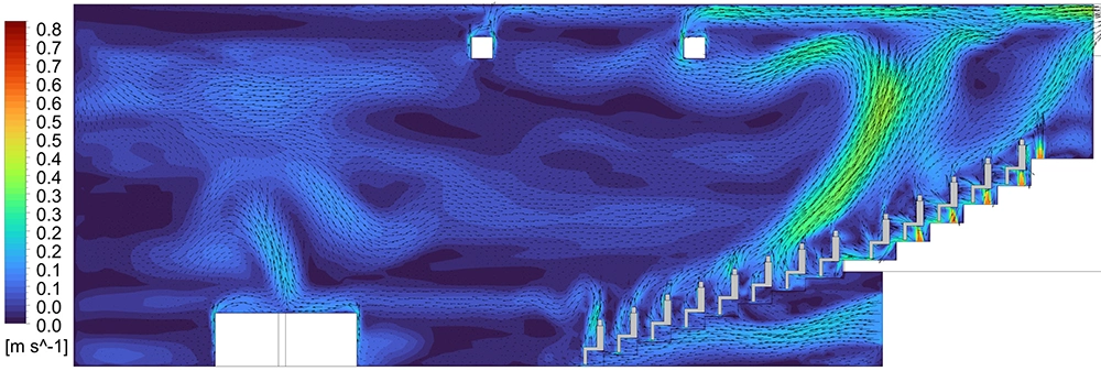
For Option 1, two supply air temperatures were evaluated (19 °C and 23 °C) to assess the sensitivity of the temperature distribution to the inlet conditions. Option 2 was analysed at 19 °C. Velocity contour plots, velocity vectors and temperature contour plots were extracted on multiple cross-sections through the audience zone to reveal flow patterns, recirculation zones and thermal stratification.
Transient warm-up analysis
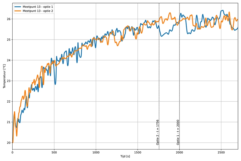
Starting from an initial room temperature of 20 °C with a supply air temperature of 19 °C, we ran time-dependent simulations for both extraction options to determine exactly when and where the 26 °C threshold is first reached. Thirteen monitoring points were placed at audience head height across all rows of the grandstand, from the lowest to the highest row, to track the temperature evolution over time.
Results
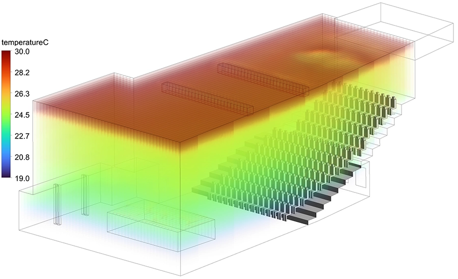
The steady-state analyses confirmed that both extraction layouts maintain the audience zone well below 26 °C under continuous operation, with clear thermal stratification: cool supply air fills the lower grandstand area where the audience sits, while heated air rises naturally toward the ceiling and exits through the extraction outlets. This displacement ventilation pattern is exactly the behaviour required for effective audience comfort.
The transient warm-up simulations provided the critical design insight. The average room temperature converges toward approximately 25 °C for both options. However, the highest monitoring point — at the top of the grandstand, closest to the ceiling-level heat accumulation — is the first to reach the 26 °C threshold. With Option 1 (rear wall extraction), this occurs after approximately 33 minutes. With Option 2 (lateral duct extraction), the same threshold is reached earlier, after approximately 29 minutes.
Option 1 also achieved a slightly lower overall average room temperature, confirming its superior performance for this specific theater geometry. The difference is explained by the extraction location: the single rear wall opening in Option 1 sits higher, capturing the naturally rising warm air plume more effectively than the lateral ducts in Option 2.
The steady-state analysis at the higher supply air temperature of 23 °C showed that the thermal margin is significantly reduced: temperatures in the upper grandstand rows approach or exceed the comfort limit, indicating that a supply temperature of 19 °C is necessary under full occupancy to maintain acceptable conditions throughout a typical performance duration.
Value Delivered
By applying CFD simulation with coupled thermal modelling, we provided the HVAC design team with a clear, quantitative comparison of both extraction configurations — something that simplified air-change or zone-based calculations cannot deliver for a space with complex geometry, displacement ventilation and large, distributed heat sources.
The study delivered an evidence-based recommendation for the preferred extraction layout (Option 1, rear wall), a validated prediction of the time window before thermal comfort limits are exceeded, confirmation that the proposed supply air volume and temperature are adequate for full-occupancy conditions, and detailed visualisations of the flow field and temperature distribution that supported the design review with the architect and building owner.
The transient results also gave the operator a practical guideline: with the recommended extraction layout and a supply temperature of 19 °C, the theater can host performances of up to approximately 30 minutes before the highest audience rows approach the comfort threshold — valuable information for programming and intermission planning.
Need a ventilation or thermal comfort analysis for your building project?
Whether you are designing an HVAC system for a theater, auditorium, sports hall or any other occupied space, we can simulate the airflow, temperature distribution and thermal comfort before construction. We also optimise duct layouts, diffuser positions and supply conditions to achieve the best result. Get in touch for a free initial consultation.
Contact us or call us at +32 478 618 118