The Challenge
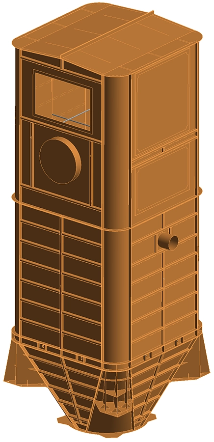
Siloba, a Belgian manufacturer of industrial storage and handling equipment, required a structural verification of a 6 m³ stainless steel silo destined for use in the food processing industry at a milling facility. The silo is designed to store fine-grain products — including materials that can generate combustible dust — and must therefore withstand not only normal operating loads but also the transient overpressure that follows the activation of its explosion relief panel.
The verification had to demonstrate compliance with the Ultimate Limit State (ULS) requirements of three Eurocodes: EN 1990 (Basis of Structural Design), EN 1991-1 (Actions on Structures) and EN 1993-4 (Design of Silos). Three distinct load cases were of interest: self-weight of the structure, hydrostatic pressure from a full product load, and the residual overpressure after the explosion panel opens. Each required a specific analysis strategy, and the governing combination had to be identified before the design could be signed off.
Our Approach
We performed a fully non-linear Finite Element Analysis in Ansys Mechanical, incorporating geometric non-linearity, non-linear contact between components, and a non-linear material model for SS304. Working with non-linear analyses was essential here: the explosion load case involves large deformations that a linear solver would significantly underestimate, and the material response needed to be tracked into the plastic range to confirm that the strain limits of the applicable standard were not exceeded.
Geometry and mesh
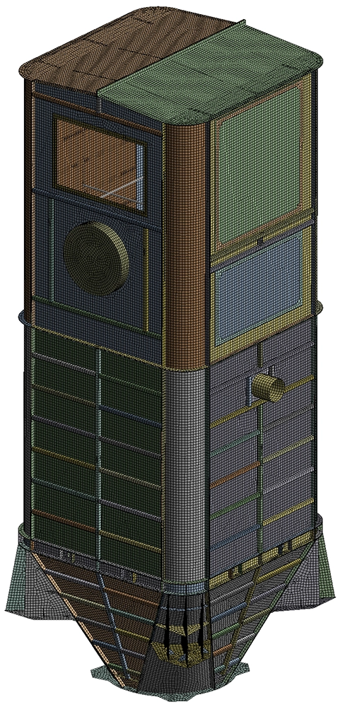
The full 3D CAD assembly supplied by the client was imported and meshed using 2D hexahedral shell elements. The mesh density was deliberately refined to capture accurate stress gradients across the thin-walled panels, the corner welds and the hopper transitions — the locations where local stress concentrations are most likely to govern the design. The silo's ten vertical M16 grade 8.8 tie rods connecting the vertical walls were modelled explicitly as circular cross-section elements.
Boundary conditions and load cases
The silo is supported vertically at four console feet, which were modelled as fixed vertical displacement constraints. Three characteristic load cases were defined in line with the applicable Eurocodes and client-specified data:
- Self-weight QG,k: applied as a gravitational body acceleration.
- Hydrostatic pressure QH,k: applied as a variable internal pressure load proportional to depth, representing the silo filled to its nominal 6 m³ capacity with a bulk product of density 750 kg/m³ — a total product mass of 4,500 kg.
- Dust explosion overpressure QA,k: a uniform internal pressure of 0.5 bar (50 kPa), representing the residual pressure pred acting on the silo walls after the explosion panel has fully opened. This value was specified by the client in accordance with the facility's explosion protection document.
Load combinations (ULS)
The three load cases were combined into three ULS load combinations with Eurocode partial safety factors, targeting the governing scenario for each failure mode:
| Combination | Self-weight QG,k | Hydrostatic QH,k | Explosion QA,k | Design intent |
|---|---|---|---|---|
| BC 1 | 1.15 | 0 | 0 | Self-weight only — baseline stiffness |
| BC 2 | 1.15 | 1.15 | 0 | Normal operation — full product load |
| BC 3 | 1.15 | 0 | 1.0 | Accidental — dust explosion event |
Results
BC 1 and BC 2 — Normal operating conditions
Under self-weight alone (BC 1), the silo is extremely stiff: the maximum total deformation is only 0.17 mm, and the maximum Von Mises stress reaches 20 MPa — well within the allowable stress of 187 MPa for SS304 (yield strength 215 MPa ÷ partial factor 1.15). The dominant deformation occurs at the circular inlet on the upper body, where the ring stiffening is locally less effective.
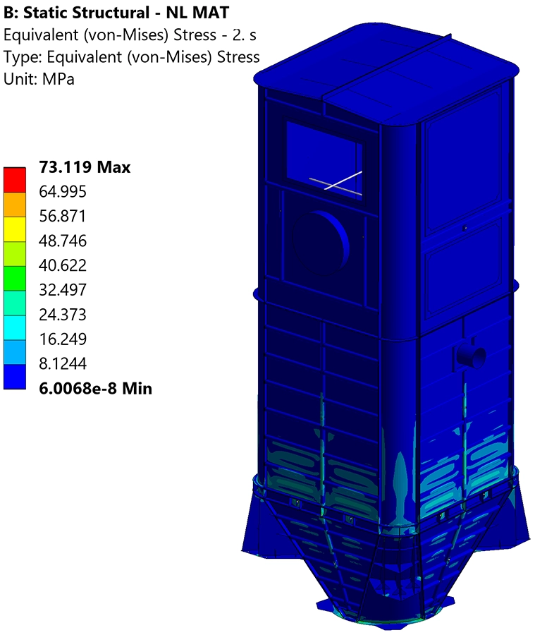
Adding the full hydrostatic product pressure (BC 2) increases the maximum deformation to 1.7 mm and the peak Von Mises stress to 73 MPa, both still comfortably within limits. The largest stresses develop in the lower hopper panels and at the console connection zones, where the combination of self-weight and product pressure generates the highest membrane and bending stress resultants.
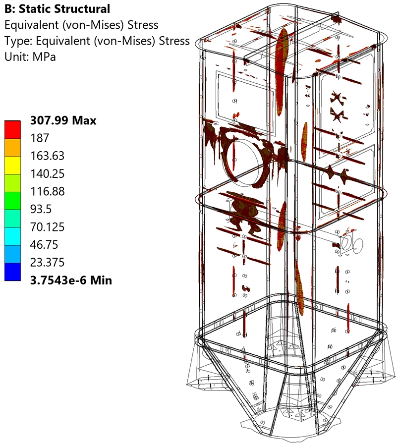
BC 3 — Dust explosion accidental load
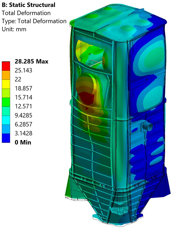
The explosion load combination is the governing case and required the most careful assessment. The uniform 0.5 bar internal overpressure drives the silo walls outward, producing a maximum total deformation of 28 mm, concentrated at the access hatch (manway) opening in the upper body — a geometrically compliant area where the panel is locally unsupported. The peak Von Mises stress reaches 308 MPa, which exceeds the design allowable of 187 MPa.
However, this result is permissible under the accidental load provisions of EN 1993-1-5, Annex C.8, which allows stresses above the yield limit for accidental load cases provided two conditions are simultaneously satisfied: the stress must remain below the material ultimate tensile strength, and the maximum principal elastic strain must not exceed 5%. Both conditions are met:
- Maximum Von Mises stress: 308 MPa < 520 MPa (tensile strength of SS304) ✓
- Maximum principal elastic strain: 0.1% < 5% (per EN 1993-1-5 §C.8) ✓
Tie rod check
The ten M16 grade 8.8 tie rods connecting the vertical wall panels were verified analytically in accordance with EN 1993-1-8. The design tensile resistance of each rod (Ft,Rd = 90.4 kN) exceeds the maximum axial force extracted from the FEA model (49.2 kN), confirming adequate margin under the governing explosion load combination.
Value Delivered
By running a non-linear FEA rather than a simplified hand-calculation approach, we were able to capture the true structural response of the silo across all three load cases — including the plastic deformation behaviour under the accidental explosion scenario that a linear analysis would not have represented correctly. The isosurface plots and strain maps provided the evidence needed to demonstrate compliance with EN 1993-1-5 Annex C, something that is not achievable with classical strength calculation methods alone.
The deliverable was a fully documented structural verification report containing geometry descriptions, material data, load case definitions, load combinations, contour plots for all results, and a clear pass/fail assessment table. This documentation package can be submitted directly to the client's notified body or internal quality review process.
The analysis confirmed that the silo satisfies both the stiffness and strength requirements of the applicable Eurocodes across all three governing load combinations, and that the explosion relief design functions as intended: the panel opens before the wall stresses approach the tensile strength of the material, and the resulting deformations remain within the limits accepted by the standard.
Need a structural FEA verification for a silo, vessel or storage structure?
Whether you are designing to EN 1993-4, PED, or a client-specific standard, our team can deliver a complete FEA-based structural verification — from geometry import and meshing through to the final compliance report. Get in touch for a free initial consultation.
Contact us or call us at +32 478 618 118