The Challenge
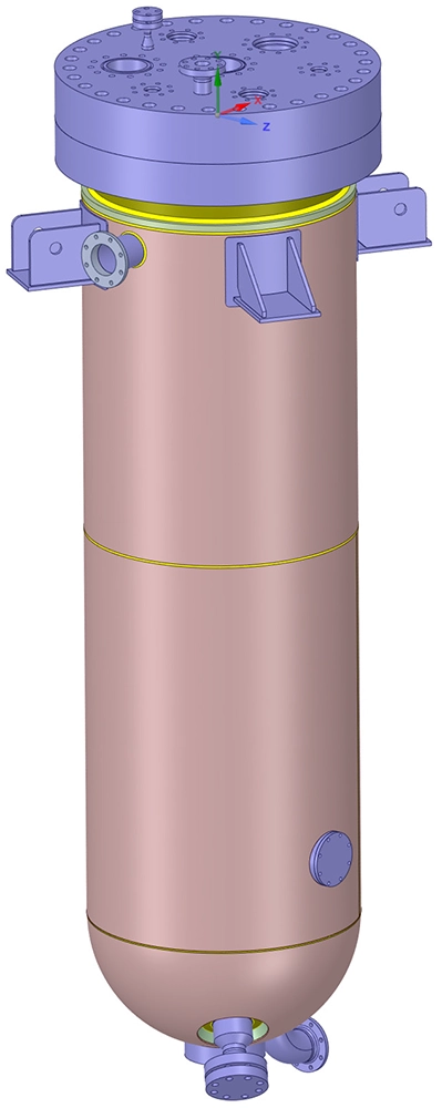
A manufacturer of process equipment needed to verify whether the welds in a jacketed reactor vessel could withstand the fatigue loading imposed by its operational process cycle. The vessel — a reactor surrounded by a heating/cooling jacket — is manufactured entirely from S32205 duplex stainless steel and operates under repeated thermal and pressure cycles.
During each 396-minute process cycle, the temperatures in the jacket and reactor vary significantly: the jacket inner wall cycles between approximately 15 °C and 90 °C, while the reactor inner wall drops from 80 °C to as low as 14 °C before recovering. Simultaneously, the internal pressure in both the jacket and reactor fluctuates according to the process requirements. These combined cyclic thermal and mechanical loads generate complex, time-varying stress fields — particularly at the welded connections between the reactor, jacket shell, nozzles and bottom heads.
The critical question: do the 15 welds under investigation meet the required minimum fatigue life of 29,200 cycles according to EN 13445-3, Chapter 18 (Detailed Assessment of Fatigue Life)?
Our Approach
The analysis followed a structured three-step workflow, coupling a transient thermal analysis with a structural finite element analysis and a subsequent weld fatigue assessment. Each step feeds its results into the next, ensuring the full interaction between thermal and mechanical loads is captured accurately.
Step 1 — Transient thermal analysis
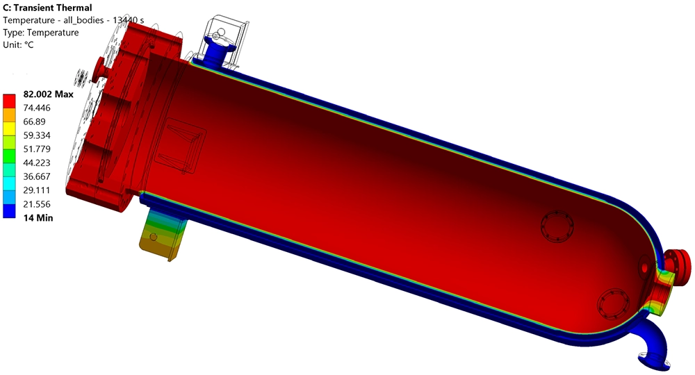
The complete vessel geometry was modelled in Ansys Mechanical, including the reactor, jacket, nozzles, supports and flanges. Time-varying temperature boundary conditions were applied to the inner walls of the jacket and the inner wall of the reactor, representing one full process cycle. The initial temperature of all components was set to 80 °C. The solver computed the temperature distribution through the entire vessel wall thickness at every time step throughout the 396-minute cycle.
Step 2 — Structural FEA
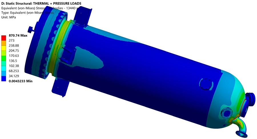
The transient temperature field from Step 1 was imported into a static structural analysis in Ansys Mechanical. At each time step, the model simultaneously accounts for thermal stresses caused by non-uniform temperature distributions and differential expansion, internal pressure loads on the jacket and reactor walls (both time-varying), and nozzle loads on the agitator flange, side jacket connection, bottom nozzle and bottom pad. The vessel is supported vertically at four points while remaining free to expand and contract horizontally, accurately representing the real support conditions.
Step 3 — Weld fatigue assessment per EN 13445-3
Using the time-varying stress results from Step 2, the fatigue life of each weld was evaluated in nCode DesignLife using the structural hot spot stress method. Stress combination was based on the absolute maximum principal stress. Each weld was classified according to its weld detail and testing group as specified in EN 13445-3, Table 18.4, and assigned the corresponding FAT curve. Correction factors for wall thickness and mean stress were applied; a temperature correction was not required since all operating temperatures remain below 100 °C.
Results
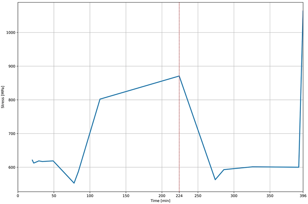
The transient thermal analysis revealed that the largest temperature difference across the vessel occurs at t = 224 min into the process cycle. At that instant, the jacket remains at approximately 82 °C while the reactor body has cooled to just 14 °C — a gradient of nearly 68 °C across the shared wall and bottom head connections. A second critical moment occurs at t = 396 min, when a sudden temperature drop in the jacket generates a sharp thermal transient in the bottom head region.
The structural analysis confirmed that these thermal gradients drive the peak stresses: Von Mises stresses exceeding 870 MPa were recorded at the most constrained locations — well above the material's yield strength of 450 MPa. While localised plastic stress redistribution would occur in practice, the linear elastic stress results are used as input for the fatigue assessment according to EN 13445-3, which accounts for this through the hot spot extrapolation method.
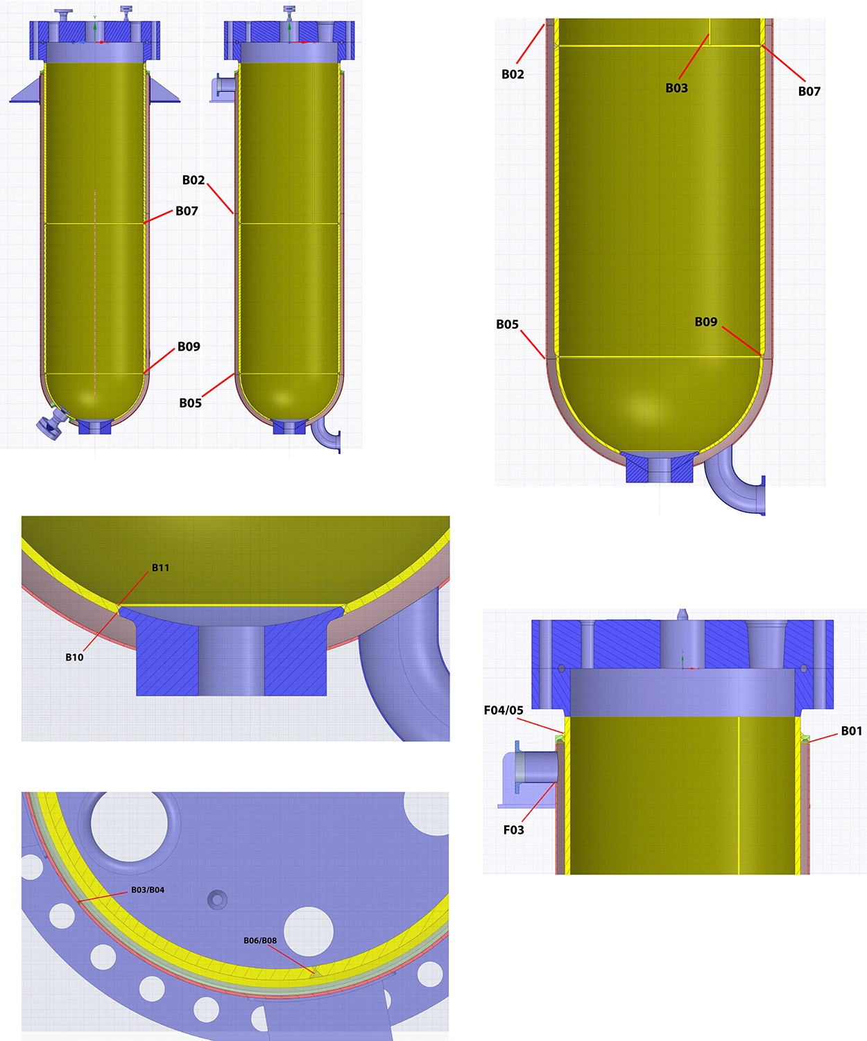
The fatigue assessment of all 15 welds produced the following key findings. Five welds exceeded the required fatigue life of 29,200 cycles comfortably, with welds B01, B02, B03, B04 and B05 all achieving between 90,800 and over 7.3 million cycles. However, seven welds fell below the required life: welds B06, B08, B09, B10, F03 and F04/05 ranged from approximately 5,150 to 13,650 cycles — significantly short of the 29,200-cycle target. Weld F09 at the bottom pad connection was found to exceed the static strength limit, indicating failure under the applied loads without any fatigue cycling at all.
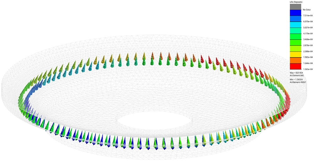
A critical insight emerged when the thermal and mechanical load contributions were separated: stresses from the pressure loading alone produced acceptable fatigue lives for all welds. The dominant cause of fatigue failure was the cyclic thermal loading — specifically the large temperature differences between the jacket and reactor during certain phases of the process cycle. This finding directly points the way to potential design improvements: reducing the thermal gradient severity or modifying the geometry at the most affected weld locations.
Value Delivered
By coupling transient thermal simulation with structural FEA and a detailed weld fatigue assessment per EN 13445-3, we provided the client with a complete picture of the vessel's fatigue performance under realistic operating conditions. The analysis went beyond a simple pass/fail outcome — it identified exactly which welds are critical, quantified how far they fall short of the required fatigue life, and pinpointed thermal loading as the root cause.
These results enable the manufacturer to make informed engineering decisions: whether to modify the weld geometry at specific locations, adjust the process cycle to reduce peak thermal gradients, or strengthen the most affected connections. Without this integrated simulation approach — combining thermal, structural and fatigue disciplines in a single workflow — it would not have been possible to isolate the thermal contribution and identify the most effective path to a compliant design.
Need a fatigue assessment for your pressure vessel or welded structure?
We specialise in combined thermal, structural and fatigue analyses for pressure equipment, reactors and process vessels — per EN 13445, ASME and other codes. Explore our fatigue services or get in touch for a free initial consultation.
Contact us or call us at +32 478 618 118