The Challenge
NURESYS BV, a specialist in water and sludge treatment, upgraded an existing stainless steel stripping tank in Apeldoorn (NL) by adding eight process tubes and nozzles at the bottom of the vessel. Before the modification could be put into service, the updated structure had to be formally verified for structural integrity under the full range of in-service loads.
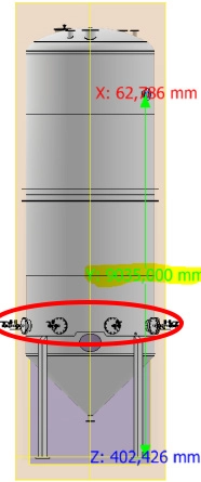
The tank is a large cylindrical vessel — approximately 62,800 mm tall with a diameter of 3,200 mm — fabricated from stainless steel grades S304L (1.4301) and S316L (1.4404). It stores liquid at a density of 1,200 kg/m³, is exposed to Dutch wind and snow climate loads, and must accommodate personnel access at the top. The design had to satisfy both the stiffness (SLS) and strength (ULS) requirements of Eurocode 3 (EN 1993) — specifically EN 1993-1-4 for stainless steel structures — with a maximum allowable stress of 209 MPa.
The client needed more than a simplified hand calculation: the complex geometry of the conical lower section, the eight new bottom connections, and the combination of hydrostatic, wind and snow loads called for a full finite element analysis.
Our Approach
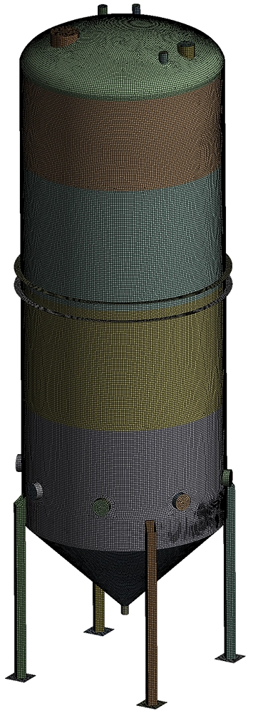
The full geometry of the tank — as provided by the client in STEP format — was meshed and solved in Ansys Mechanical using a linear static solver supplemented by a non-linear buckling analysis. The approach was structured to cover every loading scenario required by Eurocode 3.
Shell element mesh
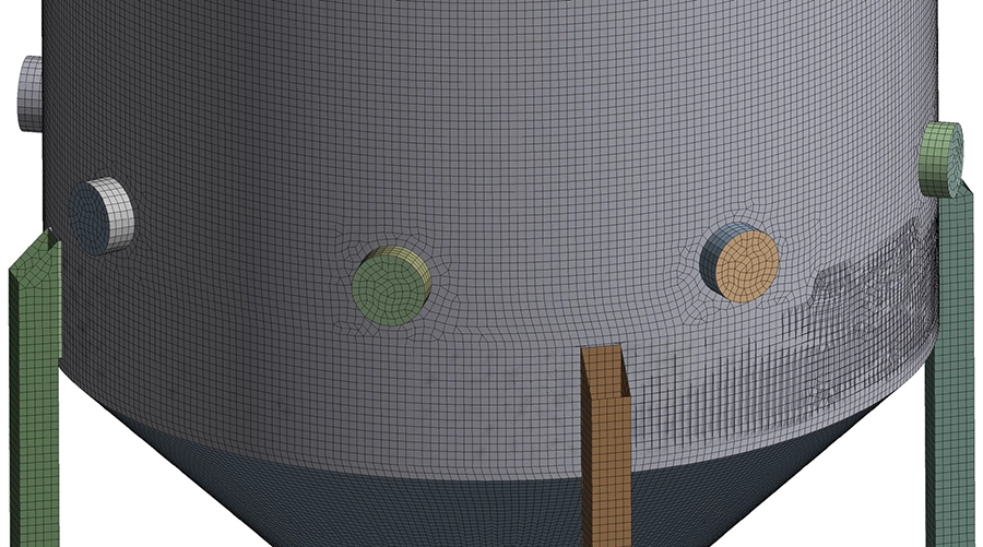
All plates, structural profiles and the eight new tubes were meshed with linear 2D shell elements. This element type is well suited to thin-walled pressure vessels and structural containers: it captures membrane and bending behaviour accurately while keeping the model computationally efficient. A local mesh refinement was applied around the eight new connections at the bottom of the tank, where stress concentrations were expected.
Loads and boundary conditions
The tank is fixed at the base of its four support legs. Five independent load types were applied and subsequently combined into SLS and ULS load combinations following the Eurocode partial-factor method:
- Self-weight — applied as a gravitational acceleration (9,810 mm/s²).
- Hydrostatic pressure — internal liquid pressure from a fluid density of 1,200 kg/m³ up to a maximum fill height of 9,035 mm above the base of the tank.
- Wind load — calculated per EN 1991-1-4 for the Apeldoorn site (base wind speed 24.5 m/s, terrain category II). Two wind directions were assessed: along the X-axis and at 45° to account for the most unfavourable orientation. The resulting total wind force on the cylindrical body was 13.9 kN, with an effective wind pressure of 0.451 kN/m².
- Snow load — 0.70 kN/m² applied to the top of the tank per EN 1991-1-3 for Apeldoorn.
- Personnel load — 5.0 kN/m² on the top roof area, representing maintenance access loads.
These five loads were assembled into 6 SLS load combinations (serviceability, used to evaluate deformations) and 8 ULS load combinations (ultimate, used to evaluate stresses), using the load factors prescribed by Eurocode.
Results
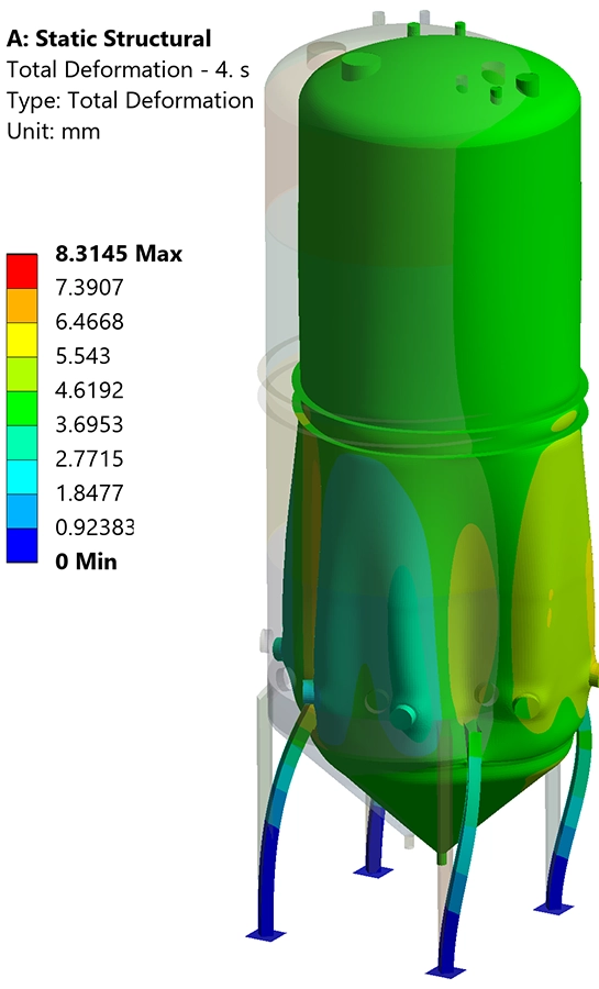
Stiffness — deformations under SLS
The maximum deformation across all six SLS combinations was 8.3 mm, occurring under SLS 04 (which combines gravity, hydrostatic and 45° wind loads at full characteristic values). This value is very small relative to the overall tank dimensions and is well within the deformation limits of EN 1993. The deformation contour plots confirmed that the largest displacements occur in the cylindrical body of the vessel under the combined action of hydrostatic pressure and lateral wind — the expected and physically correct response.
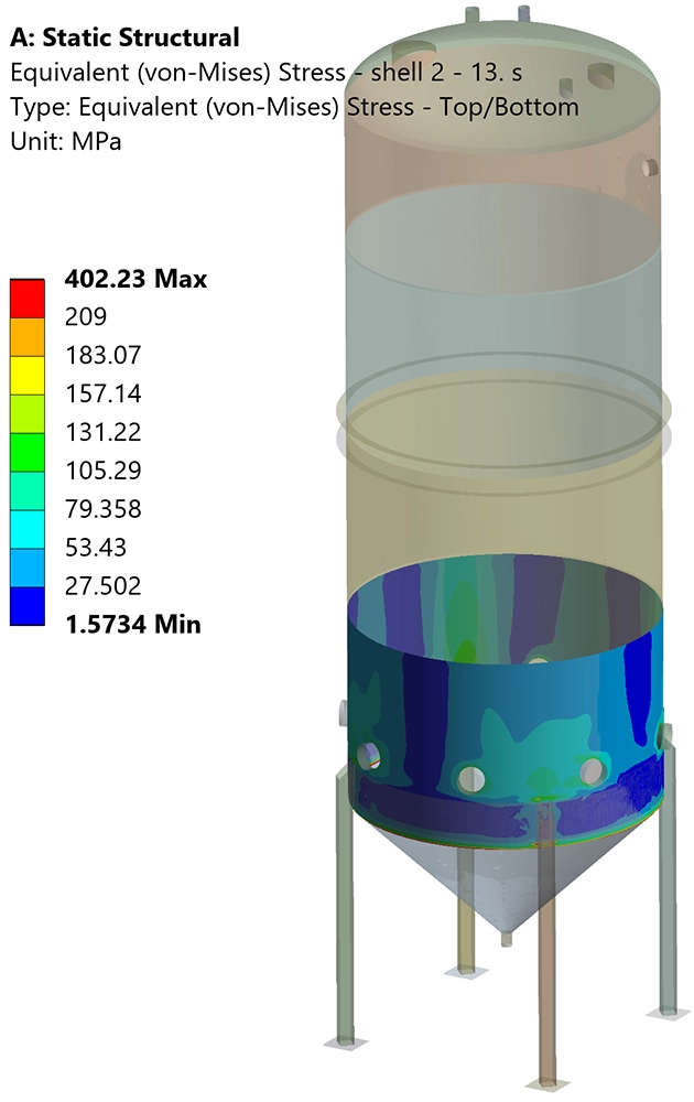
Strength — Von Mises stresses under ULS
For ULS 01, 02, 04, 05 and 06, the maximum equivalent (Von Mises) stress remained comfortably below the allowable 209 MPa across the entire structure, including the eight new bottom connections. Peak values in these combinations ranged from 7 MPa (gravity-only) to 79 MPa (wind-dominant).
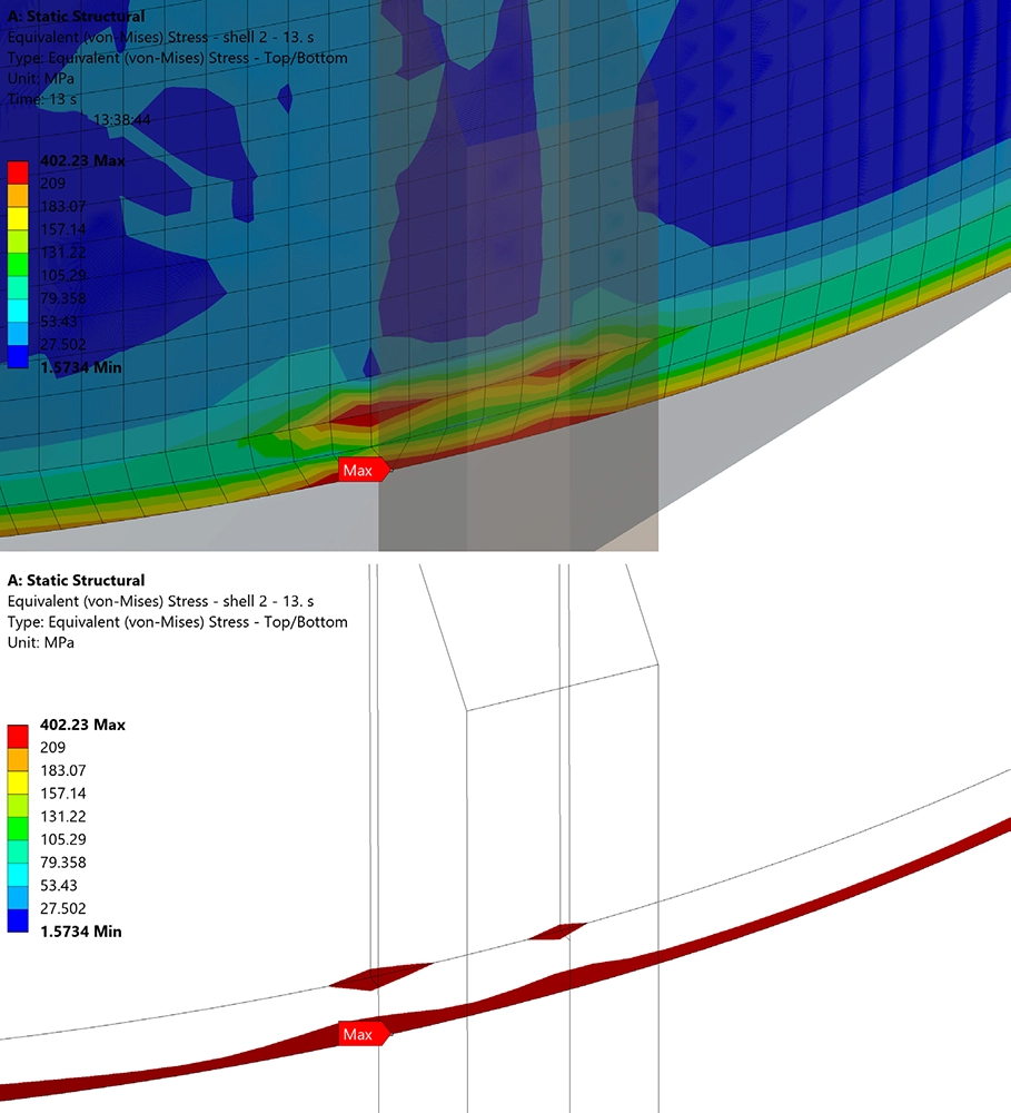
For ULS 03, 07 and 08 — the combinations that include both the full hydrostatic load and either wind or personnel loads at ULS factors — the contour plots showed localised stress peaks exceeding the 209 MPa threshold. A detailed investigation using zoomed contour plots and isosurface plots of the region where stresses exceeded 209 MPa confirmed that these peaks are confined to a single row of elements at a geometric intersection. They are classical numerical artefacts of the finite element method at shell-to-shell junctions and are not representative of real physical stress. Excluding these singularities, the structure meets the strength criteria in all eight ULS combinations.
Value Delivered
The analysis provided NURESYS BV with a formally documented structural verification report confirming that the upgraded stripping tank satisfies all stiffness and strength requirements of Eurocode 3. The client received clear evidence — with full load combination matrices, contour plots and isosurface visualisations — to support sign-off and commissioning.
Critically, the use of shell-element FEA rather than a simplified beam or hand-calculation approach gave the necessary spatial resolution to assess the eight new bottom connections individually, identify the governing load combinations, and correctly distinguish true structural stress from numerical artefacts. This level of detail would not have been achievable with analytical methods alone.
The approach is equally applicable to other storage vessels, pressure equipment and structural containers in the process industry. If you need a similar structural verification — whether for a new design, a design modification or a periodic assessment — our team can help.
Need a structural verification for process equipment?
Whether you need to verify a tank, pressure vessel or supporting structure against Eurocode, ASME or another standard, we deliver clear, documented analysis you can use directly. Get in touch for a free initial discussion.
Contact us or call us at +32 478 618 118