Expert partner in calculating material fatigue
Quadco Engineering is your leading partner in the advanced world of fatigue analysis and predicting metal fatigue. With a rich history of over 15 years in delivering unparalleled expertise and advice, we are committed to maximizing the durability and reliability of your products and structures. Our comprehensive service offering covers all aspects of fatigue analysis, from stress-life and strain-life analyses to specialized evaluations for weld joints and composites, providing a solid foundation for your projects across various industrial sectors.
Innovative solutions for your material fatigue challenges
Our approach is rooted in a deep understanding of the complex nature of fatigue and the challenges it presents. By integrating advanced software tools such as nCode DesignLife, Ansys Mechanical, and Nastran, we aim to provide realistic and accurate lifespan predictions essential for the success of your projects.
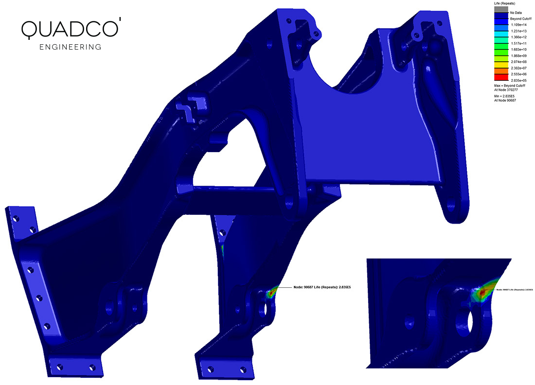
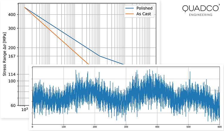
- Stress-life (S-N) and strain-life (E-N) analysis: Our analyses cover both high-cycle and low-cycle fatigue problems, applying advanced material models and fatigue corrections to deliver the most accurate results. These methods are crucial for determining the fatigue life of components under varying load conditions.
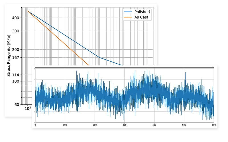
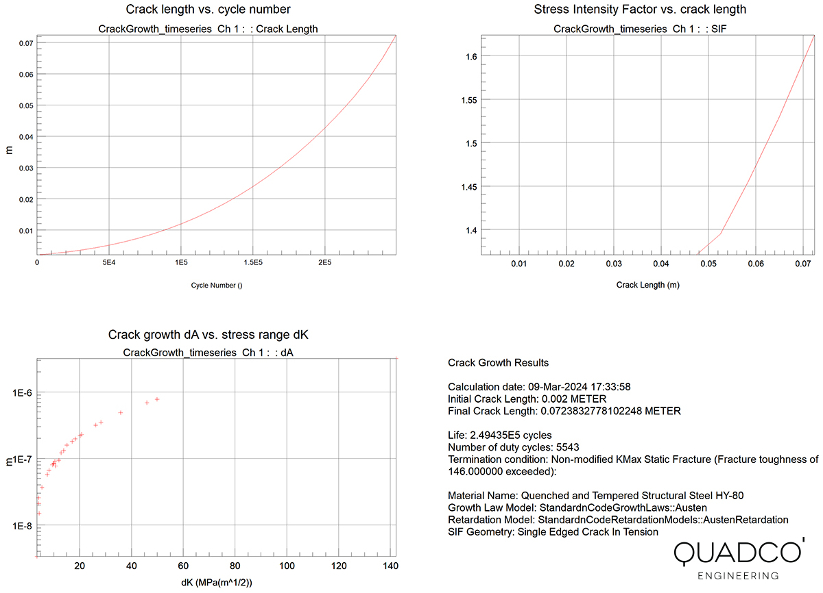
The assumption made in the S-N and E-N fatigue analysis method is that fatigue failure occurs once a crack has formed, visible to the naked eye, typically 1-2 mm in size. - Crack growth analysis: When a fatigue crack has initiated (or is already present), we can also calculate the remaining lifetime during the crack growth phase. Some materials exhibit high resistance to further crack growth and can therefore have a significant reamining life after the crack initiation periode calculated with the S-N or E-N analysis methods. This approach fundamentally differs from the S-N and E-N methods and is based on fracture mechanics.
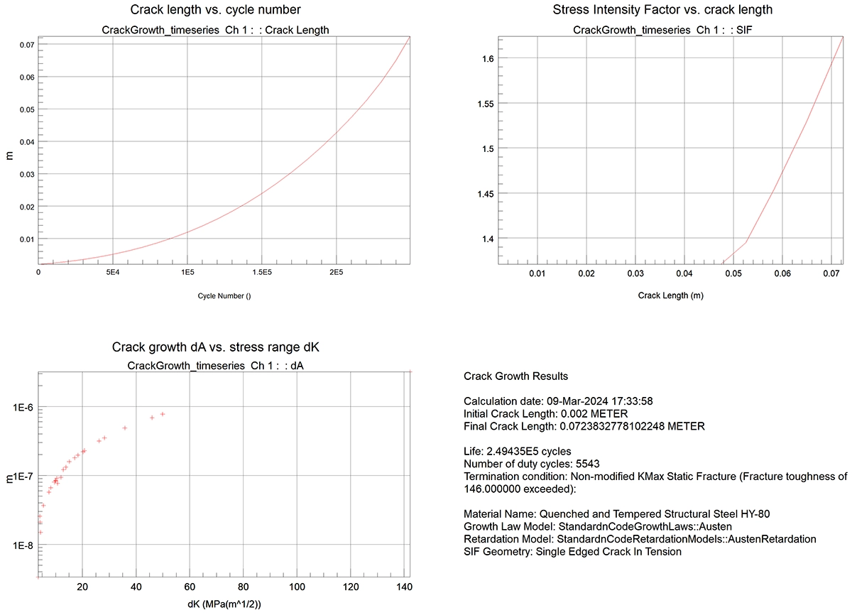
After the initiating of a fatigue crack, the crack continues to grow until it potentially reaches a critical length, leading to the complete failure of the material in fatigue. - Vibration fatigue: We offer advanced analysis of virtual shaker table tests and predict material fatigue in the frequency domain. This approach is particularly effective for evaluating random loads, such as those caused by wind and wave loads, providing more efficient and realistic results than traditional time-domain analyses
- Thermo-mechanic fatigue: Our expertise extends to the assessment of components exposed to high temperatures and creep, which is crucial for parts such as combustion engines, exhaust systems, and fired pressure vessels in the process industry. These analyses help predict complex failure modes under extreme thermal and mechanical conditions.
- Fatigue of welded joints: We offer specialized analyses of welded structures,with seam welds or spot welds, evaluating the lifetime of welded components using advanced methods that take into account the unique properties and challenges of welded constructions.
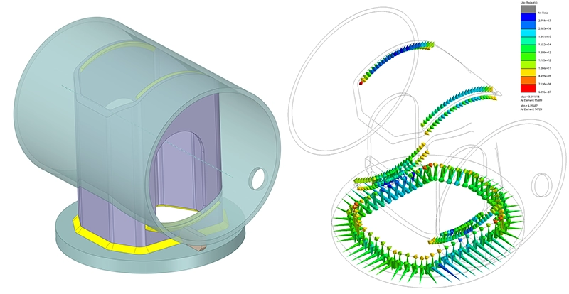
Fatigue life analysis of the seam welds in a welded component. The fatigue life is calculated both at the weld toe and the weld root. - Fatigue of composites: Our approach for composites includes a stress-life analysis for anisotropic materials, such as short-fiber composites. We evaluate the fatigue strength of structures against industry-standard composite failure criteria, effectively identifying critical locations and load combinations.

Commitment to excellence and innovation
Our engineers are dedicated to continuously improving our services and innovating in our methods and techniques. Our engineers are experts in using the finite element method (FEA, FEM, EEM) and other advanced techniques to analyze complex fatigue problems. We constantly invest in the latest simulation and analysis technologies to report our advice and findings to our clients in a clear and organized manner.
Collaborating with Quadco Engineering
Choose Quadco Engineering as your trusted partner in the complex world of calculating metal fatigue and material fatigue. With our extensive experience, advanced software tools, and commitment to your success, we are ready to analyze all structural durability problems and provide you with expert advice and guidance in your design and product development processes.
Contact us today at contact for a quote or a non-binding appointment, and discover how we can support you in achieving your goals with our comprehensive expertise and advice in calculating fatigue and metal fatigue.